How to Select a Bakery Conveyor Chain
Practical measurement and selection guidance.
Read GuideEngineering
Measurement, selection, integration and maintenance guidance for industrial bakery conveyor chains.
Practical measurement and selection guidance.
Read GuidePractical measurement and selection guidance.
Read GuidePractical measurement and selection guidance.
Read GuidePractical measurement and selection guidance.
Read GuidePractical measurement and selection guidance.
Read GuidePractical measurement and selection guidance.
Read GuidePractical measurement and selection guidance.
Read GuidePractical measurement and selection guidance.
Read GuidePractical measurement and selection guidance.
Read GuidePractical measurement and selection guidance.
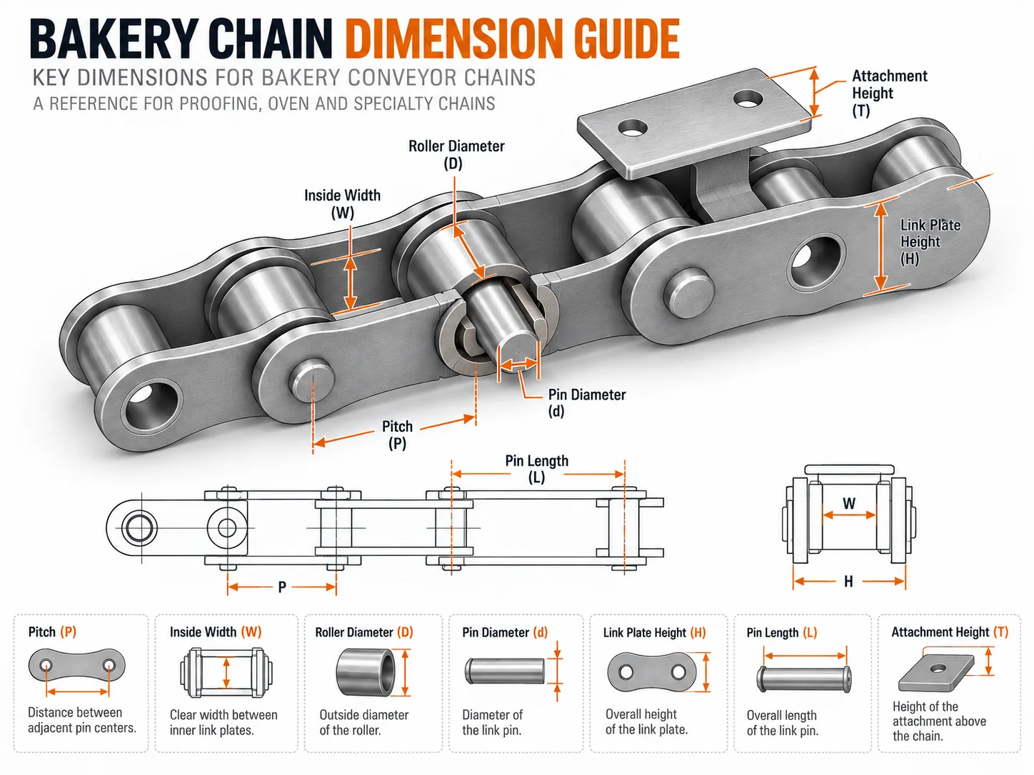
Read GuideReplacement projects are faster when the RFQ contains reproducible dimensions. Record pitch, inside width, roller or bush diameter, pin diameter, plate geometry and the exact attachment pattern. Then add sprocket tooth count, chain centers and application conditions.
Use the replacement measurement guide to prepare the data.
These guides help identify the likely chain family and the questions that must be resolved. They do not replace the final approved drawing or application review. Material, working rating, clearance, lubrication and attachment details are confirmed for the ordered configuration.
Use pitch, inside width, roller or bush size, pin dimensions and plate geometry to identify what is installed.
Inspect sprockets, guides, take-up and carrier interfaces so wear or tracking problems are not attributed to the strand alone.
Turn the field record into one controlled RFQ and drawing review. Keep fixed interchange dimensions separate from material, attachment and service options.
Measure several pitches rather than one worn joint. Record inside width, roller or bush diameter, pin size, plate height and overall width. If attachments are present, include their offset, hole pattern and repeated interval. These are the dimensions another engineer should be able to reproduce.
Show drive and tail sprockets, guides, wear strips, carrier bars, chain centers and take-up. A chain that matches the catalogue dimensions can still be wrong if a pin projection, attachment bend or roller location conflicts with the installed machine envelope.
Noise, apparent elongation, stiff joints and side wear are observations, not diagnoses. Compare location and pattern. A symptom concentrated at one sprocket or guide suggests a different investigation from uniform wear along the whole strand.
State running and peak temperature, moisture or cleaning exposure, speed, start/stop behavior, supported load and lubrication limitations. Record the machine state in which the problem occurs so hot, wet and shutdown conditions are not mixed together.
Use the measured geometry and duty to narrow standard conveyor, proofer, oven, stainless, hollow-pin, attachment, double-pitch or custom options. A shortlist is not an interchange guarantee; it is the point at which the RFQ becomes specific enough for drawing review.
Mark must-match dimensions and selectable options on one revision. Confirm carrier fit, sprocket engagement and required documentation before ordering. Keep the approved drawing with the maintenance baseline so future replacement work starts from controlled data.
Provide a dimensioned sketch or marked drawing with the measurement method. Avoid relying on an isolated part number when the installed chain is worn or the machine has been modified.
Include one full machine-zone view, one chain-on-sprocket view, several pitches from the side, an end view of transverse geometry and the carrier or attachment interface.
State speed, load, temperature by zone, humidity or washdown, cleaning chemistry where relevant, lubrication practice and start/stop frequency.
State required length or quantity, whether a sample is needed, target schedule and any material or inspection documents required with the order.
Start with identification: photograph the complete machine zone and measure several pitches, inside width, roller or bush diameter, pin geometry and plate height. Then use the identification and replacement guides to build a shortlist. Do not let a stamped code or historical name override measured geometry when the machine has been modified or the strand is worn.
Start with diagnosis before specification. Map where the symptom appears, inspect sprocket teeth, guide contact, shaft alignment, take-up reserve and carrier squareness, then compare loaded and return runs. The maintenance, sprocket and alignment guides help decide whether the chain is the cause, a victim of another defect, or only one part of a system-level problem.
Start with the actual duty cycle. Record normal and peak temperature, exposure duration, condensation or cleaning chemistry, drying condition and lubrication restrictions. Use the oven/high-temperature and stainless-material guides to decide what needs further review while keeping the machine’s fixed geometry separate from environmental options.
Start with the load path through the carrier. Record attachment hole pattern and bend direction, pin or bore size, cross-rod details, chain-center distance and repeated interval. Use the attachment and hollow-pin guides to verify that the proposed interface does not restrict articulation or introduce side load into parallel strands.
Finish by consolidating maintenance observations, engineering dimensions and purchasing quantity into one request. The goal is a drawing that states fixed interchange dimensions and ordered options clearly. Review that drawing against the machine before approval, then keep it with the baseline inspection record for future maintenance and replacement decisions.
Engineering decision tools is most reliable when the process, chain and machine are reviewed as one mechanism.
Use measurements and machine-side evidence to turn an unknown or worn chain into a reviewable specification. Record the actual conveyor section rather than describing the entire bakery line with one operating condition.
Pitch, transverse width, roller or bush size, pin dimensions, sprocket geometry and attachment locations are the starting facts for compatibility.
State speed, supported load or carrier mass, temperature, humidity, cleaning and lubrication constraints. These details decide which options deserve review.
Send drawings and context photographs together. Keep fixed dimensions separate from options that may be optimized so the final drawing can be checked efficiently.