Record geometry
Pitch, width, roller/bush, pin, plate, overall width and attachment pattern.
Bakery Chain Technical Guide
Information to Send When Requesting a Replacement Chain is best answered by combining measured chain geometry, machine duty and the operating environment. This guide shows what to inspect, record and discuss before a replacement or new-chain decision.
Information to Send When Requesting a Replacement Chain should be evaluated from the actual conveyor. Start with chain pitch, transverse geometry, sprocket condition and any carrier attachment, then add temperature, moisture, washdown, load, speed and take-up information. The objective is not to identify a chain by appearance; it is to produce an RFQ that preserves the machine interface and makes application-dependent choices explicit.
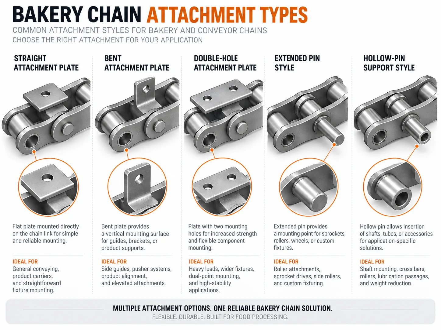
Measure several characteristics before removing the chain. Pitch locates the basic gearing relationship, but inside width, roller or bush diameter, pin diameter, plate height, overall width and attachment dimensions distinguish configurations that can share the same nominal pitch.
For a worn strand, measure cumulative pitch across multiple links. Photograph the chain from the side and end, and include the sprocket where practical.

The same chain geometry can behave differently in a humid proofer, a hot oven, an ambient cooling section or a washdown area. For information to send when requesting a replacement chain, document the exact machine zone, whether the chain carries product directly or moves pans/fixtures, and whether the joint sees heat, moisture, cleaning chemicals or abrasive residue.
Process data helps determine which characteristics are fixed by interchangeability and which characteristics—such as material, clearance or attachment manufacturing method—should be reviewed for the application.
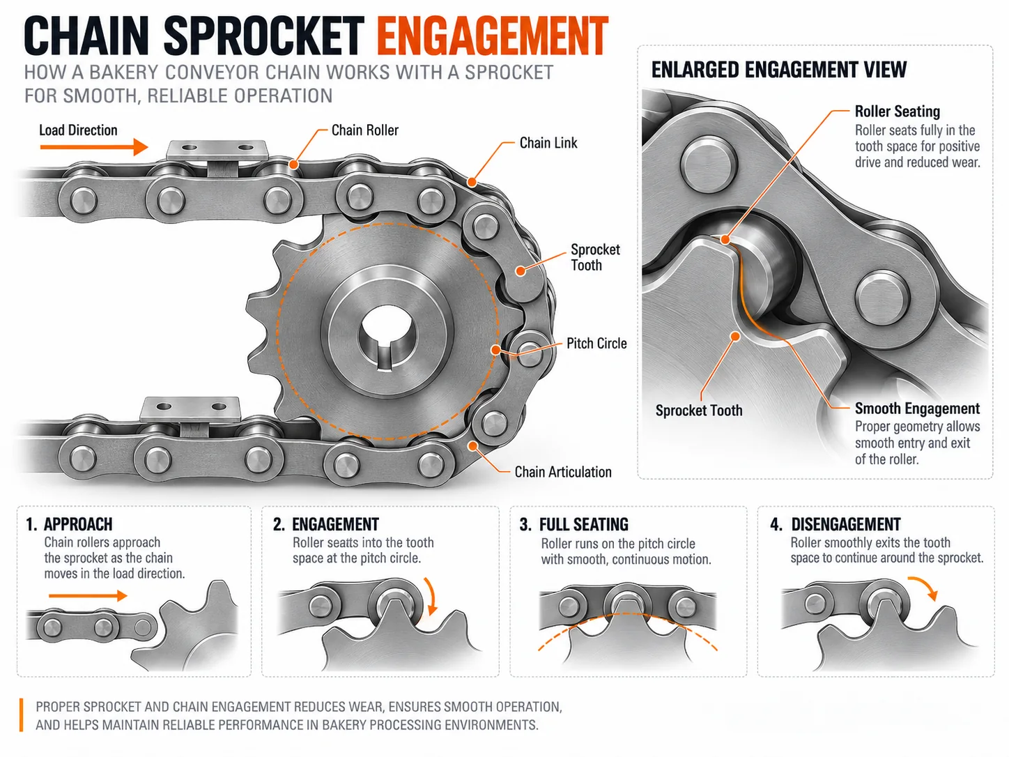
A chain does not operate independently. Rollers or bushes must enter and leave the sprocket tooth spaces smoothly, while guide tracks support the strand without forcing it sideways. Hooked teeth, shaft misalignment, eccentric sprockets or a tight guide can make a new chain wear quickly.
Inspect the complete path through one full circuit. If damage repeats at the same machine location, investigate the local support, transfer or carrier before assuming the chain itself is defective.
Pitch, width, roller/bush, pin, plate, overall width and attachment pattern.
Temperature, moisture, washdown, speed, load, production hours and starts.
Sprockets, guides, chain centers, take-up, alignment and carrier clearances.
Approve the final ordered geometry, material and application-dependent configuration before installation.
Ask what changed before the problem appeared: production rate, product or pan weight, cleaning cycle, lubricant, temperature, maintenance interval or replaced sprockets. Trend information is more valuable than a single photograph because it shows whether wear is uniform or concentrated.
During routine inspection, look for stiff joints, roller wear, pin movement, cracked or bent attachments, abnormal side contact and uneven take-up. Keep guards and safety procedures in place according to the machine owner’s requirements.
Include the measured dimensions, machine/process name, photos, drawing if available, quantity or required chain length, attachment interval, chain-center spacing, sprocket information, temperature, washdown condition, load and target delivery window. Review the przewodnik po wyborze sieci piekarni and the product-family overview for the next decision step.
A useful diagnosis starts with evidence that can be repeated by a second person. assembling an RFQ package that lets an engineer identify the chain and its machine interface. Record multi-pitch length, inside width, roller/bush diameter, pin dimensions, plate geometry, attachment spacing and chain centers. When the chain is worn, note which readings may be influenced by joint clearance or deformation, and prefer multi-pitch or multi-point measurements over one isolated dimension.
The chain does not operate by itself. In any bakery conveyor where the original part number or supplier is uncertain, inspect the sprockets, guides, return path, take-up and carrier interface at the same time. The symptom to watch is slow quotation cycles or wrong matches caused by incomplete dimensions and isolated close-up photos. A local problem that repeats at one machine position often points to alignment, clearance or mating-hardware issues rather than a uniform chain problem.
The practical decision is to send a reproducible dimension set together with machine context, operating conditions and quantity. That prevents a common error: changing chain tension, material or size before the root constraint has been identified. Use the chain drawing and the machine envelope together, because a configuration that looks correct in isolation can still interfere with a guard, transfer plate, sensor bracket or carrier.
Describe the operating cycle rather than a single adjective such as “hot,” “wet” or “food grade.” State normal and peak temperature where relevant, moisture or cleaning exposure, speed, start/stop behavior and lubrication limitations. These details decide whether clearances, materials or maintenance practice need to change while the basic geometry remains fixed.
| Sprawdzać | Dlaczego to ważne | Co wysłać lub zweryfikować |
|---|---|---|
| Identification | Confirm multi-pitch length, inside width, roller/bush diameter, pin dimensions, plate geometry, attachment spacing and chain centers. Use a measurement sequence that can be repeated after removal so the installed and bench readings can be compared. | Dimensioned sketch, scale-aware photos and any legacy drawing or part number. |
| Route position | Map where the chain runs through any bakery conveyor where the original part number or supplier is uncertain. Mark the exact location of slow quotation cycles or wrong matches caused by incomplete dimensions and isolated close-up photos instead of reporting the condition only as a whole-line problem. | Context photo showing the conveyor section, drive/tail positions and return path. |
| Mating parts | Inspect tooth profile, roller seating, shaft/sprocket alignment, guide contact and take-up reserve. These parts can create wear patterns that imitate a chain-selection problem. | Sprocket tooth count and photos, guide layout and current take-up position. |
| Load path | Identify how product carriers, pans, rods or fixtures transfer load into the chain. For this topic, the key focus is assembling an RFQ package that lets an engineer identify the chain and its machine interface. | Carrier drawing, attachment interval, chain-center spacing and supported mass/force where known. |
| Środowisko | Record temperature, humidity, washdown, contamination and lubrication restrictions by machine zone. Separate continuous exposure from short peaks or cleaning events. | Operating-condition summary and maintenance/lubrication practice. |
| Release | The final engineering action is to send a reproducible dimension set together with machine context, operating conditions and quantity. The approved drawing should distinguish fixed interchange dimensions from selectable options. | dimensioned sketch, context/close-up photos, application, environment, sprocket data, quantity and documentation needs. |
A uniform change along the whole strand suggests a different mechanism from damage concentrated at one sprocket, guide or transfer. For Information to Send When Requesting a Replacement Chain, compare left/right sides and loaded/return paths. The distribution of wear can reveal whether the driver is joint wear, side loading, contamination, thermal change or a carrier that is forcing the chain out of its natural path.
Increasing tension can temporarily change noise or tracking without correcting the underlying cause. If the observed issue is slow quotation cycles or wrong matches caused by incomplete dimensions and isolated close-up photos, first confirm alignment, take-up geometry and articulation. Excessive tension can add bearing load and make a marginal guide or attachment problem worse.
Bakery equipment can move between production, cleaning and shutdown states. A chain may articulate normally when cool and become tight when heated, or run freely during production but corrode after repeated wet shutdowns. Record the state in which the symptom occurs so the selected corrective action addresses the real duty cycle.
For an unknown chain, one close-up is not enough. Pair a complete machine-zone image with side and end views of several pitches, a sprocket-engagement photo and a clear attachment/carrier view. Place a scale only where it does not hide the feature being measured. This photo set makes assembling an RFQ package that lets an engineer identify the chain and its machine interface easier to evaluate remotely.
Record multi-pitch length, inside width, roller/bush diameter, pin dimensions, plate geometry, attachment spacing and chain centers, chain centers, sprocket tooth count and the carrier interface before changing components.
Describe what happens in any bakery conveyor where the original part number or supplier is uncertain, including temperature or moisture changes, speed, load and cleaning/lubrication constraints.
Document where slow quotation cycles or wrong matches caused by incomplete dimensions and isolated close-up photos appears. Compare drive, tail, loaded run, return run and transfer points rather than averaging the entire conveyor.
Include dimensioned sketch, context/close-up photos, application, environment, sprocket data, quantity and documentation needs. State the required quantity or chain length and any documentation needed with the order.
Review pitch, widths, pin/roller geometry, attachments and material notes on one controlled drawing revision. For Information to Send When Requesting a Replacement Chain, the release decision should explicitly address assembling an RFQ package that lets an engineer identify the chain and its machine interface.
After installation, observe at least one full circuit, check sprocket entry/exit and carrier clearance, and recheck take-up according to the machine maker’s procedure. New chain should not be used to compensate for worn or misaligned hardware.
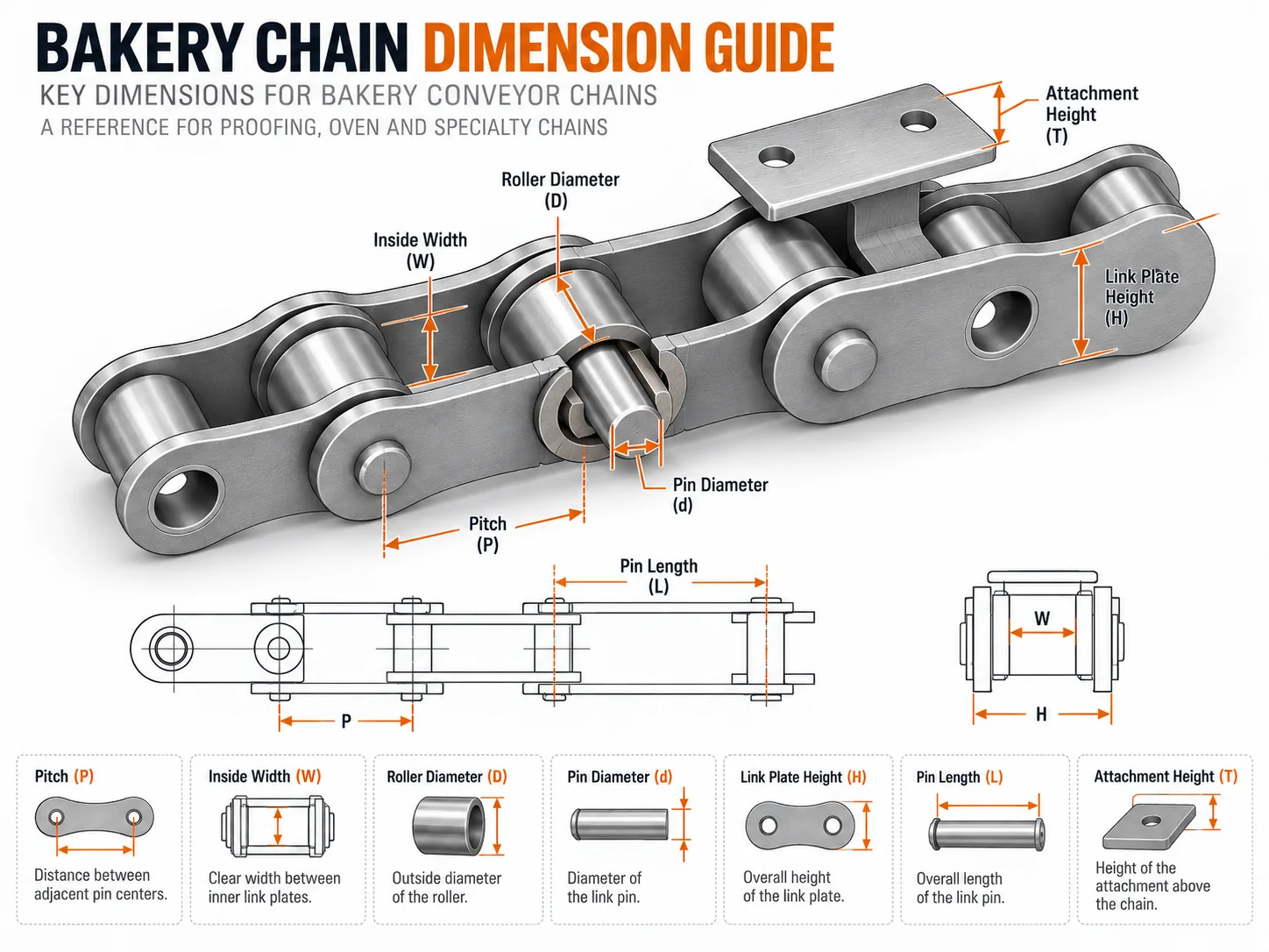
The main reason to keep this process structured is that assembling an RFQ package that lets an engineer identify the chain and its machine interface interacts with more than one component. A change that improves one symptom can shift load into another part of the mechanism. For example, correcting guide alignment may reduce side wear but also expose a take-up setting that was previously compensating for the misalignment. Record changes one at a time so the result can be interpreted.
For planned maintenance, compare the present condition with a baseline whenever one exists. If there is no baseline, create one during the next shutdown: photograph the sprockets and guide surfaces, record take-up position, measure a defined number of pitches, and note the chain’s location in any bakery conveyor where the original part number or supplier is uncertain. Repeating the same observations later is more informative than relying on general statements such as “the chain has stretched.”
When an existing drawing is available, verify that the installed hardware still matches it. Bakery equipment is often modified over its service life: carriers can be repaired, guide rails moved, sprockets replaced, and attachment intervals changed. The drawing remains useful, but field verification prevents a historical document from being treated as proof of the current configuration.
Procurement and engineering should use the same evidence package. The RFQ should not separate commercial quantity from technical context: dimensioned sketch, context/close-up photos, application, environment, sprocket data, quantity and documentation needs. This makes it possible to judge whether a standard series, a modified attachment or a custom replacement is the appropriate route without creating unnecessary back-and-forth.
Finally, treat the website as a preparation tool rather than the controlling product drawing. Measurements and diagrams narrow the family and help organize the RFQ; the released drawing defines the ordered configuration. That distinction is especially important where slow quotation cycles or wrong matches caused by incomplete dimensions and isolated close-up photos could have more than one mechanical cause.
Use Information to Send When Requesting a Replacement Chain as a machine-level question, not just a chain inspection. Compare the loaded and return runs, drive and tail ends, and any transfer or carrier transition in any bakery conveyor where the original part number or supplier is uncertain. Document whether slow quotation cycles or wrong matches caused by incomplete dimensions and isolated close-up photos is distributed along the strand or repeats at one location. That pattern helps separate progressive joint wear from alignment, guide, sprocket or carrier problems that a new chain alone will not correct.
The working record should include multi-pitch length, inside width, roller/bush diameter, pin dimensions, plate geometry, attachment spacing and chain centers. Mark which values are fixed by the existing machine and which values can be changed to improve service. The central engineering focus is assembling an RFQ package that lets an engineer identify the chain and its machine interface. When a legacy part number conflicts with field measurements, hold the RFQ until the installed interface and the controlled drawing can be reconciled.
A useful enquiry combines commercial quantity with the technical package: dimensioned sketch, context/close-up photos, application, environment, sprocket data, quantity and documentation needs. Also state whether the request is a direct replacement, a planned modification or a new machine design. The release objective is to send a reproducible dimension set together with machine context, operating conditions and quantity. This reduces quote revisions and prevents a visually similar chain from being treated as interchangeable before geometry and duty have been checked.
Use the old reference if available, but verify the installed geometry and duty. Machine modifications, previous substitutions or wear can make a part number alone incomplete.
Use a multi-pitch measurement across a practical number of links and record the method. Compare it with the nominal pitch and machine maintenance limits rather than relying on one adjacent-link measurement.
Whenever tooth wear, hooking, alignment concerns or repeated premature chain wear are present. The chain and sprocket work as a meshing system.
Bakery Chain Technical Guide
When to Replace Chain and Sprockets Together is best answered by combining measured chain geometry, machine duty and the operating environment. This guide shows what to inspect, record and discuss before a replacement or new-chain decision.
When to Replace Chain and Sprockets Together should be evaluated from the actual conveyor. Start with chain pitch, transverse geometry, sprocket condition and any carrier attachment, then add temperature, moisture, washdown, load, speed and take-up information. The objective is not to identify a chain by appearance; it is to produce an RFQ that preserves the machine interface and makes application-dependent choices explicit.
Measure several characteristics before removing the chain. Pitch locates the basic gearing relationship, but inside width, roller or bush diameter, pin diameter, plate height, overall width and attachment dimensions distinguish configurations that can share the same nominal pitch.
For a worn strand, measure cumulative pitch across multiple links. Photograph the chain from the side and end, and include the sprocket where practical.

The same chain geometry can behave differently in a humid proofer, a hot oven, an ambient cooling section or a washdown area. For when to replace chain and sprockets together, document the exact machine zone, whether the chain carries product directly or moves pans/fixtures, and whether the joint sees heat, moisture, cleaning chemicals or abrasive residue.
Process data helps determine which characteristics are fixed by interchangeability and which characteristics—such as material, clearance or attachment manufacturing method—should be reviewed for the application.
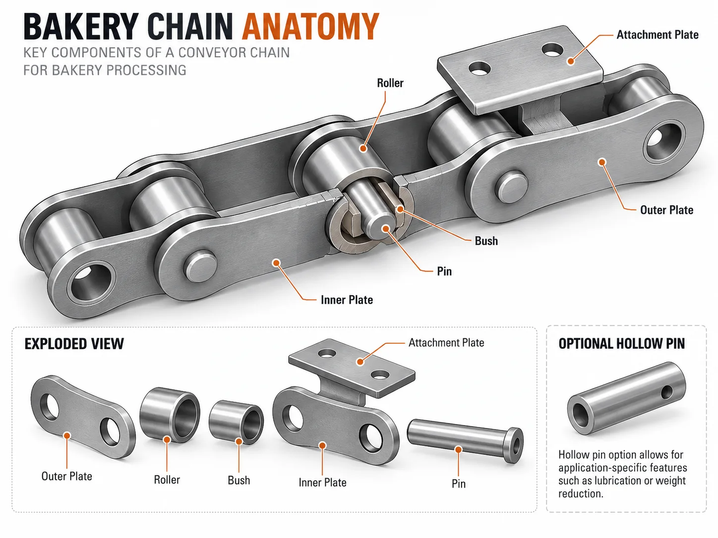
A chain does not operate independently. Rollers or bushes must enter and leave the sprocket tooth spaces smoothly, while guide tracks support the strand without forcing it sideways. Hooked teeth, shaft misalignment, eccentric sprockets or a tight guide can make a new chain wear quickly.
Inspect the complete path through one full circuit. If damage repeats at the same machine location, investigate the local support, transfer or carrier before assuming the chain itself is defective.
Pitch, width, roller/bush, pin, plate, overall width and attachment pattern.
Temperature, moisture, washdown, speed, load, production hours and starts.
Sprockets, guides, chain centers, take-up, alignment and carrier clearances.
Approve the final ordered geometry, material and application-dependent configuration before installation.
Ask what changed before the problem appeared: production rate, product or pan weight, cleaning cycle, lubricant, temperature, maintenance interval or replaced sprockets. Trend information is more valuable than a single photograph because it shows whether wear is uniform or concentrated.
During routine inspection, look for stiff joints, roller wear, pin movement, cracked or bent attachments, abnormal side contact and uneven take-up. Keep guards and safety procedures in place according to the machine owner’s requirements.
Include the measured dimensions, machine/process name, photos, drawing if available, quantity or required chain length, attachment interval, chain-center spacing, sprocket information, temperature, washdown condition, load and target delivery window. Review the przewodnik po wyborze sieci piekarni and the product-family overview for the next decision step.
A useful diagnosis starts with evidence that can be repeated by a second person. deciding whether worn tooth geometry will shorten the life of a replacement chain. Record chain elongation, tooth hooking, roller seating, backlash, alignment and service history. When the chain is worn, note which readings may be influenced by joint clearance or deformation, and prefer multi-pitch or multi-point measurements over one isolated dimension.
The chain does not operate by itself. In maintenance shutdowns on established bakery conveyors, inspect the sprockets, guides, return path, take-up and carrier interface at the same time. The symptom to watch is new chain riding high or seating irregularly in old tooth spaces. A local problem that repeats at one machine position often points to alignment, clearance or mating-hardware issues rather than a uniform chain problem.
The practical decision is to replace both when sprocket wear is sufficient to prevent correct seating or reliable load sharing. That prevents a common error: changing chain tension, material or size before the root constraint has been identified. Use the chain drawing and the machine envelope together, because a configuration that looks correct in isolation can still interfere with a guard, transfer plate, sensor bracket or carrier.
Describe the operating cycle rather than a single adjective such as “hot,” “wet” or “food grade.” State normal and peak temperature where relevant, moisture or cleaning exposure, speed, start/stop behavior and lubrication limitations. These details decide whether clearances, materials or maintenance practice need to change while the basic geometry remains fixed.
| Sprawdzać | Dlaczego to ważne | Co wysłać lub zweryfikować |
|---|---|---|
| Identification | Confirm chain elongation, tooth hooking, roller seating, backlash, alignment and service history. Use a measurement sequence that can be repeated after removal so the installed and bench readings can be compared. | Dimensioned sketch, scale-aware photos and any legacy drawing or part number. |
| Route position | Map where the chain runs through maintenance shutdowns on established bakery conveyors. Mark the exact location of new chain riding high or seating irregularly in old tooth spaces instead of reporting the condition only as a whole-line problem. | Context photo showing the conveyor section, drive/tail positions and return path. |
| Mating parts | Inspect tooth profile, roller seating, shaft/sprocket alignment, guide contact and take-up reserve. These parts can create wear patterns that imitate a chain-selection problem. | Sprocket tooth count and photos, guide layout and current take-up position. |
| Load path | Identify how product carriers, pans, rods or fixtures transfer load into the chain. For this topic, the key focus is deciding whether worn tooth geometry will shorten the life of a replacement chain. | Carrier drawing, attachment interval, chain-center spacing and supported mass/force where known. |
| Środowisko | Record temperature, humidity, washdown, contamination and lubrication restrictions by machine zone. Separate continuous exposure from short peaks or cleaning events. | Operating-condition summary and maintenance/lubrication practice. |
| Release | The final engineering action is to replace both when sprocket wear is sufficient to prevent correct seating or reliable load sharing. The approved drawing should distinguish fixed interchange dimensions from selectable options. | chain wear data, sprocket photos/tooth count, replacement history and duty conditions. |
A uniform change along the whole strand suggests a different mechanism from damage concentrated at one sprocket, guide or transfer. For When to Replace Chain and Sprockets Together, compare left/right sides and loaded/return paths. The distribution of wear can reveal whether the driver is joint wear, side loading, contamination, thermal change or a carrier that is forcing the chain out of its natural path.
Increasing tension can temporarily change noise or tracking without correcting the underlying cause. If the observed issue is new chain riding high or seating irregularly in old tooth spaces, first confirm alignment, take-up geometry and articulation. Excessive tension can add bearing load and make a marginal guide or attachment problem worse.
Bakery equipment can move between production, cleaning and shutdown states. A chain may articulate normally when cool and become tight when heated, or run freely during production but corrode after repeated wet shutdowns. Record the state in which the symptom occurs so the selected corrective action addresses the real duty cycle.
For an unknown chain, one close-up is not enough. Pair a complete machine-zone image with side and end views of several pitches, a sprocket-engagement photo and a clear attachment/carrier view. Place a scale only where it does not hide the feature being measured. This photo set makes deciding whether worn tooth geometry will shorten the life of a replacement chain easier to evaluate remotely.
Record chain elongation, tooth hooking, roller seating, backlash, alignment and service history, chain centers, sprocket tooth count and the carrier interface before changing components.
Describe what happens in maintenance shutdowns on established bakery conveyors, including temperature or moisture changes, speed, load and cleaning/lubrication constraints.
Document where new chain riding high or seating irregularly in old tooth spaces appears. Compare drive, tail, loaded run, return run and transfer points rather than averaging the entire conveyor.
Include chain wear data, sprocket photos/tooth count, replacement history and duty conditions. State the required quantity or chain length and any documentation needed with the order.
Review pitch, widths, pin/roller geometry, attachments and material notes on one controlled drawing revision. For When to Replace Chain and Sprockets Together, the release decision should explicitly address deciding whether worn tooth geometry will shorten the life of a replacement chain.
After installation, observe at least one full circuit, check sprocket entry/exit and carrier clearance, and recheck take-up according to the machine maker’s procedure. New chain should not be used to compensate for worn or misaligned hardware.
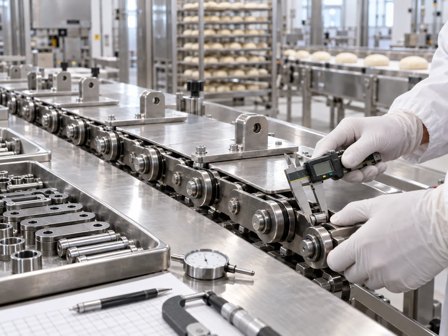
The main reason to keep this process structured is that deciding whether worn tooth geometry will shorten the life of a replacement chain interacts with more than one component. A change that improves one symptom can shift load into another part of the mechanism. For example, correcting guide alignment may reduce side wear but also expose a take-up setting that was previously compensating for the misalignment. Record changes one at a time so the result can be interpreted.
For planned maintenance, compare the present condition with a baseline whenever one exists. If there is no baseline, create one during the next shutdown: photograph the sprockets and guide surfaces, record take-up position, measure a defined number of pitches, and note the chain’s location in maintenance shutdowns on established bakery conveyors. Repeating the same observations later is more informative than relying on general statements such as “the chain has stretched.”
When an existing drawing is available, verify that the installed hardware still matches it. Bakery equipment is often modified over its service life: carriers can be repaired, guide rails moved, sprockets replaced, and attachment intervals changed. The drawing remains useful, but field verification prevents a historical document from being treated as proof of the current configuration.
Procurement and engineering should use the same evidence package. The RFQ should not separate commercial quantity from technical context: chain wear data, sprocket photos/tooth count, replacement history and duty conditions. This makes it possible to judge whether a standard series, a modified attachment or a custom replacement is the appropriate route without creating unnecessary back-and-forth.
Finally, treat the website as a preparation tool rather than the controlling product drawing. Measurements and diagrams narrow the family and help organize the RFQ; the released drawing defines the ordered configuration. That distinction is especially important where new chain riding high or seating irregularly in old tooth spaces could have more than one mechanical cause.
Use When to Replace Chain and Sprockets Together as a machine-level question, not just a chain inspection. Compare the loaded and return runs, drive and tail ends, and any transfer or carrier transition in maintenance shutdowns on established bakery conveyors. Document whether new chain riding high or seating irregularly in old tooth spaces is distributed along the strand or repeats at one location. That pattern helps separate progressive joint wear from alignment, guide, sprocket or carrier problems that a new chain alone will not correct.
The working record should include chain elongation, tooth hooking, roller seating, backlash, alignment and service history. Mark which values are fixed by the existing machine and which values can be changed to improve service. The central engineering focus is deciding whether worn tooth geometry will shorten the life of a replacement chain. When a legacy part number conflicts with field measurements, hold the RFQ until the installed interface and the controlled drawing can be reconciled.
A useful enquiry combines commercial quantity with the technical package: chain wear data, sprocket photos/tooth count, replacement history and duty conditions. Also state whether the request is a direct replacement, a planned modification or a new machine design. The release objective is to replace both when sprocket wear is sufficient to prevent correct seating or reliable load sharing. This reduces quote revisions and prevents a visually similar chain from being treated as interchangeable before geometry and duty have been checked.
Use the old reference if available, but verify the installed geometry and duty. Machine modifications, previous substitutions or wear can make a part number alone incomplete.
Use a multi-pitch measurement across a practical number of links and record the method. Compare it with the nominal pitch and machine maintenance limits rather than relying on one adjacent-link measurement.
Whenever tooth wear, hooking, alignment concerns or repeated premature chain wear are present. The chain and sprocket work as a meshing system.
Bakery Chain Technical Guide
How Chain Alignment Affects Bakery Conveyor Life is best answered by combining measured chain geometry, machine duty and the operating environment. This guide shows what to inspect, record and discuss before a replacement or new-chain decision.
How Chain Alignment Affects Bakery Conveyor Life should be evaluated from the actual conveyor. Start with chain pitch, transverse geometry, sprocket condition and any carrier attachment, then add temperature, moisture, washdown, load, speed and take-up information. The objective is not to identify a chain by appearance; it is to produce an RFQ that preserves the machine interface and makes application-dependent choices explicit.
Measure several characteristics before removing the chain. Pitch locates the basic gearing relationship, but inside width, roller or bush diameter, pin diameter, plate height, overall width and attachment dimensions distinguish configurations that can share the same nominal pitch.
For a worn strand, measure cumulative pitch across multiple links. Photograph the chain from the side and end, and include the sprocket where practical.
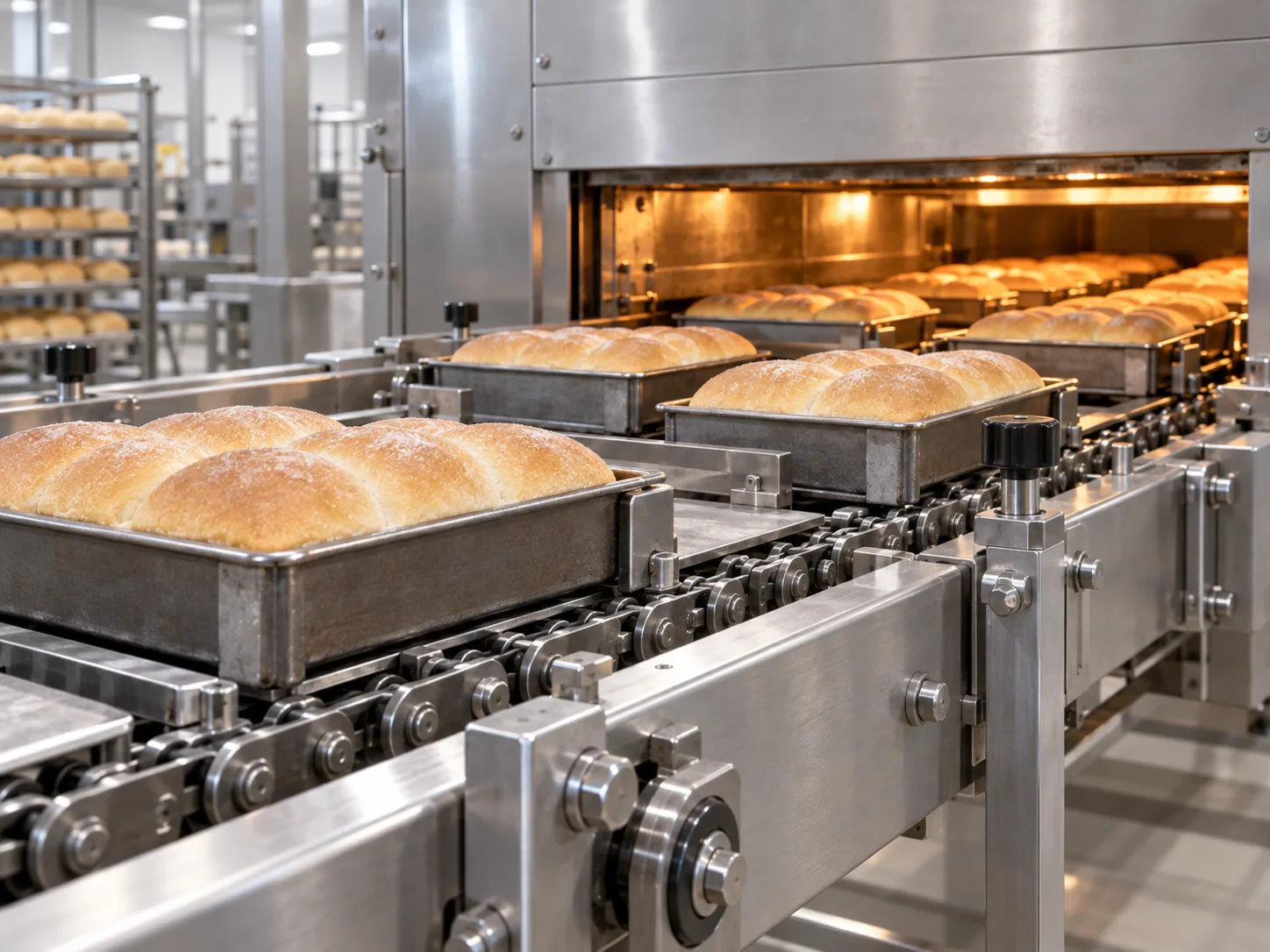
The same chain geometry can behave differently in a humid proofer, a hot oven, an ambient cooling section or a washdown area. For how chain alignment affects bakery conveyor life, document the exact machine zone, whether the chain carries product directly or moves pans/fixtures, and whether the joint sees heat, moisture, cleaning chemicals or abrasive residue.
Process data helps determine which characteristics are fixed by interchangeability and which characteristics—such as material, clearance or attachment manufacturing method—should be reviewed for the application.
A chain does not operate independently. Rollers or bushes must enter and leave the sprocket tooth spaces smoothly, while guide tracks support the strand without forcing it sideways. Hooked teeth, shaft misalignment, eccentric sprockets or a tight guide can make a new chain wear quickly.
Inspect the complete path through one full circuit. If damage repeats at the same machine location, investigate the local support, transfer or carrier before assuming the chain itself is defective.
Pitch, width, roller/bush, pin, plate, overall width and attachment pattern.
Temperature, moisture, washdown, speed, load, production hours and starts.
Sprockets, guides, chain centers, take-up, alignment and carrier clearances.
Approve the final ordered geometry, material and application-dependent configuration before installation.
Ask what changed before the problem appeared: production rate, product or pan weight, cleaning cycle, lubricant, temperature, maintenance interval or replaced sprockets. Trend information is more valuable than a single photograph because it shows whether wear is uniform or concentrated.
During routine inspection, look for stiff joints, roller wear, pin movement, cracked or bent attachments, abnormal side contact and uneven take-up. Keep guards and safety procedures in place according to the machine owner’s requirements.
Include the measured dimensions, machine/process name, photos, drawing if available, quantity or required chain length, attachment interval, chain-center spacing, sprocket information, temperature, washdown condition, load and target delivery window. Review the przewodnik po wyborze sieci piekarni and the product-family overview for the next decision step.
A useful diagnosis starts with evidence that can be repeated by a second person. understanding how shaft, sprocket, guide and carrier alignment controls side loading at the chain. Record shaft parallelism, sprocket plane, guide position, chain centers, carrier squareness and side wear. When the chain is worn, note which readings may be influenced by joint clearance or deformation, and prefer multi-pitch or multi-point measurements over one isolated dimension.
The chain does not operate by itself. In long bakery conveyors and parallel-strand carrier systems, inspect the sprockets, guides, return path, take-up and carrier interface at the same time. The symptom to watch is edge polishing, sideplate scuffing, noisy engagement or one-sided elongation. A local problem that repeats at one machine position often points to alignment, clearance or mating-hardware issues rather than a uniform chain problem.
The practical decision is to correct alignment and guide geometry before increasing tension or changing material. That prevents a common error: changing chain tension, material or size before the root constraint has been identified. Use the chain drawing and the machine envelope together, because a configuration that looks correct in isolation can still interfere with a guard, transfer plate, sensor bracket or carrier.
Describe the operating cycle rather than a single adjective such as “hot,” “wet” or “food grade.” State normal and peak temperature where relevant, moisture or cleaning exposure, speed, start/stop behavior and lubrication limitations. These details decide whether clearances, materials or maintenance practice need to change while the basic geometry remains fixed.
| Sprawdzać | Dlaczego to ważne | Co wysłać lub zweryfikować |
|---|---|---|
| Identification | Confirm shaft parallelism, sprocket plane, guide position, chain centers, carrier squareness and side wear. Use a measurement sequence that can be repeated after removal so the installed and bench readings can be compared. | Dimensioned sketch, scale-aware photos and any legacy drawing or part number. |
| Route position | Map where the chain runs through long bakery conveyors and parallel-strand carrier systems. Mark the exact location of edge polishing, sideplate scuffing, noisy engagement or one-sided elongation instead of reporting the condition only as a whole-line problem. | Context photo showing the conveyor section, drive/tail positions and return path. |
| Mating parts | Inspect tooth profile, roller seating, shaft/sprocket alignment, guide contact and take-up reserve. These parts can create wear patterns that imitate a chain-selection problem. | Sprocket tooth count and photos, guide layout and current take-up position. |
| Load path | Identify how product carriers, pans, rods or fixtures transfer load into the chain. For this topic, the key focus is understanding how shaft, sprocket, guide and carrier alignment controls side loading at the chain. | Carrier drawing, attachment interval, chain-center spacing and supported mass/force where known. |
| Środowisko | Record temperature, humidity, washdown, contamination and lubrication restrictions by machine zone. Separate continuous exposure from short peaks or cleaning events. | Operating-condition summary and maintenance/lubrication practice. |
| Release | The final engineering action is to correct alignment and guide geometry before increasing tension or changing material. The approved drawing should distinguish fixed interchange dimensions from selectable options. | alignment readings, chain centers, guide layout, wear photos and operating load. |
A uniform change along the whole strand suggests a different mechanism from damage concentrated at one sprocket, guide or transfer. For How Chain Alignment Affects Bakery Conveyor Life, compare left/right sides and loaded/return paths. The distribution of wear can reveal whether the driver is joint wear, side loading, contamination, thermal change or a carrier that is forcing the chain out of its natural path.
Increasing tension can temporarily change noise or tracking without correcting the underlying cause. If the observed issue is edge polishing, sideplate scuffing, noisy engagement or one-sided elongation, first confirm alignment, take-up geometry and articulation. Excessive tension can add bearing load and make a marginal guide or attachment problem worse.
Bakery equipment can move between production, cleaning and shutdown states. A chain may articulate normally when cool and become tight when heated, or run freely during production but corrode after repeated wet shutdowns. Record the state in which the symptom occurs so the selected corrective action addresses the real duty cycle.
For an unknown chain, one close-up is not enough. Pair a complete machine-zone image with side and end views of several pitches, a sprocket-engagement photo and a clear attachment/carrier view. Place a scale only where it does not hide the feature being measured. This photo set makes understanding how shaft, sprocket, guide and carrier alignment controls side loading at the chain easier to evaluate remotely.
Record shaft parallelism, sprocket plane, guide position, chain centers, carrier squareness and side wear, chain centers, sprocket tooth count and the carrier interface before changing components.
Describe what happens in long bakery conveyors and parallel-strand carrier systems, including temperature or moisture changes, speed, load and cleaning/lubrication constraints.
Document where edge polishing, sideplate scuffing, noisy engagement or one-sided elongation appears. Compare drive, tail, loaded run, return run and transfer points rather than averaging the entire conveyor.
Include alignment readings, chain centers, guide layout, wear photos and operating load. State the required quantity or chain length and any documentation needed with the order.
Review pitch, widths, pin/roller geometry, attachments and material notes on one controlled drawing revision. For How Chain Alignment Affects Bakery Conveyor Life, the release decision should explicitly address understanding how shaft, sprocket, guide and carrier alignment controls side loading at the chain.
After installation, observe at least one full circuit, check sprocket entry/exit and carrier clearance, and recheck take-up according to the machine maker’s procedure. New chain should not be used to compensate for worn or misaligned hardware.
The main reason to keep this process structured is that understanding how shaft, sprocket, guide and carrier alignment controls side loading at the chain interacts with more than one component. A change that improves one symptom can shift load into another part of the mechanism. For example, correcting guide alignment may reduce side wear but also expose a take-up setting that was previously compensating for the misalignment. Record changes one at a time so the result can be interpreted.
For planned maintenance, compare the present condition with a baseline whenever one exists. If there is no baseline, create one during the next shutdown: photograph the sprockets and guide surfaces, record take-up position, measure a defined number of pitches, and note the chain’s location in long bakery conveyors and parallel-strand carrier systems. Repeating the same observations later is more informative than relying on general statements such as “the chain has stretched.”
When an existing drawing is available, verify that the installed hardware still matches it. Bakery equipment is often modified over its service life: carriers can be repaired, guide rails moved, sprockets replaced, and attachment intervals changed. The drawing remains useful, but field verification prevents a historical document from being treated as proof of the current configuration.
Procurement and engineering should use the same evidence package. The RFQ should not separate commercial quantity from technical context: alignment readings, chain centers, guide layout, wear photos and operating load. This makes it possible to judge whether a standard series, a modified attachment or a custom replacement is the appropriate route without creating unnecessary back-and-forth.
Finally, treat the website as a preparation tool rather than the controlling product drawing. Measurements and diagrams narrow the family and help organize the RFQ; the released drawing defines the ordered configuration. That distinction is especially important where edge polishing, sideplate scuffing, noisy engagement or one-sided elongation could have more than one mechanical cause.
Use How Chain Alignment Affects Bakery Conveyor Life as a machine-level question, not just a chain inspection. Compare the loaded and return runs, drive and tail ends, and any transfer or carrier transition in long bakery conveyors and parallel-strand carrier systems. Document whether edge polishing, sideplate scuffing, noisy engagement or one-sided elongation is distributed along the strand or repeats at one location. That pattern helps separate progressive joint wear from alignment, guide, sprocket or carrier problems that a new chain alone will not correct.
The working record should include shaft parallelism, sprocket plane, guide position, chain centers, carrier squareness and side wear. Mark which values are fixed by the existing machine and which values can be changed to improve service. The central engineering focus is understanding how shaft, sprocket, guide and carrier alignment controls side loading at the chain. When a legacy part number conflicts with field measurements, hold the RFQ until the installed interface and the controlled drawing can be reconciled.
A useful enquiry combines commercial quantity with the technical package: alignment readings, chain centers, guide layout, wear photos and operating load. Also state whether the request is a direct replacement, a planned modification or a new machine design. The release objective is to correct alignment and guide geometry before increasing tension or changing material. This reduces quote revisions and prevents a visually similar chain from being treated as interchangeable before geometry and duty have been checked.
Use the old reference if available, but verify the installed geometry and duty. Machine modifications, previous substitutions or wear can make a part number alone incomplete.
Use a multi-pitch measurement across a practical number of links and record the method. Compare it with the nominal pitch and machine maintenance limits rather than relying on one adjacent-link measurement.
Whenever tooth wear, hooking, alignment concerns or repeated premature chain wear are present. The chain and sprocket work as a meshing system.
Bakery Chain Technical Guide
Causes of Uneven Conveyor Chain Wear is best answered by combining measured chain geometry, machine duty and the operating environment. This guide shows what to inspect, record and discuss before a replacement or new-chain decision.
Causes of Uneven Conveyor Chain Wear should be evaluated from the actual conveyor. Start with chain pitch, transverse geometry, sprocket condition and any carrier attachment, then add temperature, moisture, washdown, load, speed and take-up information. The objective is not to identify a chain by appearance; it is to produce an RFQ that preserves the machine interface and makes application-dependent choices explicit.
Measure several characteristics before removing the chain. Pitch locates the basic gearing relationship, but inside width, roller or bush diameter, pin diameter, plate height, overall width and attachment dimensions distinguish configurations that can share the same nominal pitch.
For a worn strand, measure cumulative pitch across multiple links. Photograph the chain from the side and end, and include the sprocket where practical.
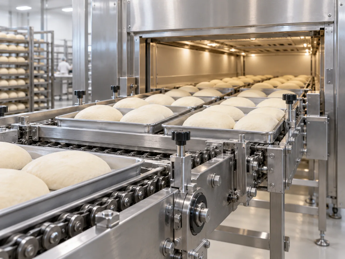
The same chain geometry can behave differently in a humid proofer, a hot oven, an ambient cooling section or a washdown area. For causes of uneven conveyor chain wear, document the exact machine zone, whether the chain carries product directly or moves pans/fixtures, and whether the joint sees heat, moisture, cleaning chemicals or abrasive residue.
Process data helps determine which characteristics are fixed by interchangeability and which characteristics—such as material, clearance or attachment manufacturing method—should be reviewed for the application.
A chain does not operate independently. Rollers or bushes must enter and leave the sprocket tooth spaces smoothly, while guide tracks support the strand without forcing it sideways. Hooked teeth, shaft misalignment, eccentric sprockets or a tight guide can make a new chain wear quickly.
Inspect the complete path through one full circuit. If damage repeats at the same machine location, investigate the local support, transfer or carrier before assuming the chain itself is defective.
Pitch, width, roller/bush, pin, plate, overall width and attachment pattern.
Temperature, moisture, washdown, speed, load, production hours and starts.
Sprockets, guides, chain centers, take-up, alignment and carrier clearances.
Approve the final ordered geometry, material and application-dependent configuration before installation.
Ask what changed before the problem appeared: production rate, product or pan weight, cleaning cycle, lubricant, temperature, maintenance interval or replaced sprockets. Trend information is more valuable than a single photograph because it shows whether wear is uniform or concentrated.
During routine inspection, look for stiff joints, roller wear, pin movement, cracked or bent attachments, abnormal side contact and uneven take-up. Keep guards and safety procedures in place according to the machine owner’s requirements.
Include the measured dimensions, machine/process name, photos, drawing if available, quantity or required chain length, attachment interval, chain-center spacing, sprocket information, temperature, washdown condition, load and target delivery window. Review the przewodnik po wyborze sieci piekarni and the product-family overview for the next decision step.
A useful diagnosis starts with evidence that can be repeated by a second person. tracing asymmetrical wear to load, alignment, guide contact, strand synchronization or localized environment. Record left/right wear pattern, chain centers, guide clearances, carrier load, sprocket alignment and take-up. When the chain is worn, note which readings may be influenced by joint clearance or deformation, and prefer multi-pitch or multi-point measurements over one isolated dimension.
The chain does not operate by itself. In parallel-strand pan, tray and general conveyor systems, inspect the sprockets, guides, return path, take-up and carrier interface at the same time. The symptom to watch is one strand elongating faster, one-sided plate wear or repeated guide scuffing. A local problem that repeats at one machine position often points to alignment, clearance or mating-hardware issues rather than a uniform chain problem.
The practical decision is to follow the wear pattern back to the machine geometry instead of correcting both strands identically. That prevents a common error: changing chain tension, material or size before the root constraint has been identified. Use the chain drawing and the machine envelope together, because a configuration that looks correct in isolation can still interfere with a guard, transfer plate, sensor bracket or carrier.
Describe the operating cycle rather than a single adjective such as “hot,” “wet” or “food grade.” State normal and peak temperature where relevant, moisture or cleaning exposure, speed, start/stop behavior and lubrication limitations. These details decide whether clearances, materials or maintenance practice need to change while the basic geometry remains fixed.
| Sprawdzać | Dlaczego to ważne | Co wysłać lub zweryfikować |
|---|---|---|
| Identification | Confirm left/right wear pattern, chain centers, guide clearances, carrier load, sprocket alignment and take-up. Use a measurement sequence that can be repeated after removal so the installed and bench readings can be compared. | Dimensioned sketch, scale-aware photos and any legacy drawing or part number. |
| Route position | Map where the chain runs through parallel-strand pan, tray and general conveyor systems. Mark the exact location of one strand elongating faster, one-sided plate wear or repeated guide scuffing instead of reporting the condition only as a whole-line problem. | Context photo showing the conveyor section, drive/tail positions and return path. |
| Mating parts | Inspect tooth profile, roller seating, shaft/sprocket alignment, guide contact and take-up reserve. These parts can create wear patterns that imitate a chain-selection problem. | Sprocket tooth count and photos, guide layout and current take-up position. |
| Load path | Identify how product carriers, pans, rods or fixtures transfer load into the chain. For this topic, the key focus is tracing asymmetrical wear to load, alignment, guide contact, strand synchronization or localized environment. | Carrier drawing, attachment interval, chain-center spacing and supported mass/force where known. |
| Środowisko | Record temperature, humidity, washdown, contamination and lubrication restrictions by machine zone. Separate continuous exposure from short peaks or cleaning events. | Operating-condition summary and maintenance/lubrication practice. |
| Release | The final engineering action is to follow the wear pattern back to the machine geometry instead of correcting both strands identically. The approved drawing should distinguish fixed interchange dimensions from selectable options. | wear map, alignment measurements, carrier drawing, sprocket photos and load distribution. |
A uniform change along the whole strand suggests a different mechanism from damage concentrated at one sprocket, guide or transfer. For Causes of Uneven Conveyor Chain Wear, compare left/right sides and loaded/return paths. The distribution of wear can reveal whether the driver is joint wear, side loading, contamination, thermal change or a carrier that is forcing the chain out of its natural path.
Increasing tension can temporarily change noise or tracking without correcting the underlying cause. If the observed issue is one strand elongating faster, one-sided plate wear or repeated guide scuffing, first confirm alignment, take-up geometry and articulation. Excessive tension can add bearing load and make a marginal guide or attachment problem worse.
Bakery equipment can move between production, cleaning and shutdown states. A chain may articulate normally when cool and become tight when heated, or run freely during production but corrode after repeated wet shutdowns. Record the state in which the symptom occurs so the selected corrective action addresses the real duty cycle.
For an unknown chain, one close-up is not enough. Pair a complete machine-zone image with side and end views of several pitches, a sprocket-engagement photo and a clear attachment/carrier view. Place a scale only where it does not hide the feature being measured. This photo set makes tracing asymmetrical wear to load, alignment, guide contact, strand synchronization or localized environment easier to evaluate remotely.
Record left/right wear pattern, chain centers, guide clearances, carrier load, sprocket alignment and take-up, chain centers, sprocket tooth count and the carrier interface before changing components.
Describe what happens in parallel-strand pan, tray and general conveyor systems, including temperature or moisture changes, speed, load and cleaning/lubrication constraints.
Document where one strand elongating faster, one-sided plate wear or repeated guide scuffing appears. Compare drive, tail, loaded run, return run and transfer points rather than averaging the entire conveyor.
Include wear map, alignment measurements, carrier drawing, sprocket photos and load distribution. State the required quantity or chain length and any documentation needed with the order.
Review pitch, widths, pin/roller geometry, attachments and material notes on one controlled drawing revision. For Causes of Uneven Conveyor Chain Wear, the release decision should explicitly address tracing asymmetrical wear to load, alignment, guide contact, strand synchronization or localized environment.
After installation, observe at least one full circuit, check sprocket entry/exit and carrier clearance, and recheck take-up according to the machine maker’s procedure. New chain should not be used to compensate for worn or misaligned hardware.
The main reason to keep this process structured is that tracing asymmetrical wear to load, alignment, guide contact, strand synchronization or localized environment interacts with more than one component. A change that improves one symptom can shift load into another part of the mechanism. For example, correcting guide alignment may reduce side wear but also expose a take-up setting that was previously compensating for the misalignment. Record changes one at a time so the result can be interpreted.
For planned maintenance, compare the present condition with a baseline whenever one exists. If there is no baseline, create one during the next shutdown: photograph the sprockets and guide surfaces, record take-up position, measure a defined number of pitches, and note the chain’s location in parallel-strand pan, tray and general conveyor systems. Repeating the same observations later is more informative than relying on general statements such as “the chain has stretched.”
When an existing drawing is available, verify that the installed hardware still matches it. Bakery equipment is often modified over its service life: carriers can be repaired, guide rails moved, sprockets replaced, and attachment intervals changed. The drawing remains useful, but field verification prevents a historical document from being treated as proof of the current configuration.
Procurement and engineering should use the same evidence package. The RFQ should not separate commercial quantity from technical context: wear map, alignment measurements, carrier drawing, sprocket photos and load distribution. This makes it possible to judge whether a standard series, a modified attachment or a custom replacement is the appropriate route without creating unnecessary back-and-forth.
Finally, treat the website as a preparation tool rather than the controlling product drawing. Measurements and diagrams narrow the family and help organize the RFQ; the released drawing defines the ordered configuration. That distinction is especially important where one strand elongating faster, one-sided plate wear or repeated guide scuffing could have more than one mechanical cause.
Use Causes of Uneven Conveyor Chain Wear as a machine-level question, not just a chain inspection. Compare the loaded and return runs, drive and tail ends, and any transfer or carrier transition in parallel-strand pan, tray and general conveyor systems. Document whether one strand elongating faster, one-sided plate wear or repeated guide scuffing is distributed along the strand or repeats at one location. That pattern helps separate progressive joint wear from alignment, guide, sprocket or carrier problems that a new chain alone will not correct.
The working record should include left/right wear pattern, chain centers, guide clearances, carrier load, sprocket alignment and take-up. Mark which values are fixed by the existing machine and which values can be changed to improve service. The central engineering focus is tracing asymmetrical wear to load, alignment, guide contact, strand synchronization or localized environment. When a legacy part number conflicts with field measurements, hold the RFQ until the installed interface and the controlled drawing can be reconciled.
A useful enquiry combines commercial quantity with the technical package: wear map, alignment measurements, carrier drawing, sprocket photos and load distribution. Also state whether the request is a direct replacement, a planned modification or a new machine design. The release objective is to follow the wear pattern back to the machine geometry instead of correcting both strands identically. This reduces quote revisions and prevents a visually similar chain from being treated as interchangeable before geometry and duty have been checked.
Use the old reference if available, but verify the installed geometry and duty. Machine modifications, previous substitutions or wear can make a part number alone incomplete.
Use a multi-pitch measurement across a practical number of links and record the method. Compare it with the nominal pitch and machine maintenance limits rather than relying on one adjacent-link measurement.
Whenever tooth wear, hooking, alignment concerns or repeated premature chain wear are present. The chain and sprocket work as a meshing system.
Bakery Chain Technical Guide
How to Inspect Chain and Sprocket Wear is best answered by combining measured chain geometry, machine duty and the operating environment. This guide shows what to inspect, record and discuss before a replacement or new-chain decision.
How to Inspect Chain and Sprocket Wear should be evaluated from the actual conveyor. Start with chain pitch, transverse geometry, sprocket condition and any carrier attachment, then add temperature, moisture, washdown, load, speed and take-up information. The objective is not to identify a chain by appearance; it is to produce an RFQ that preserves the machine interface and makes application-dependent choices explicit.
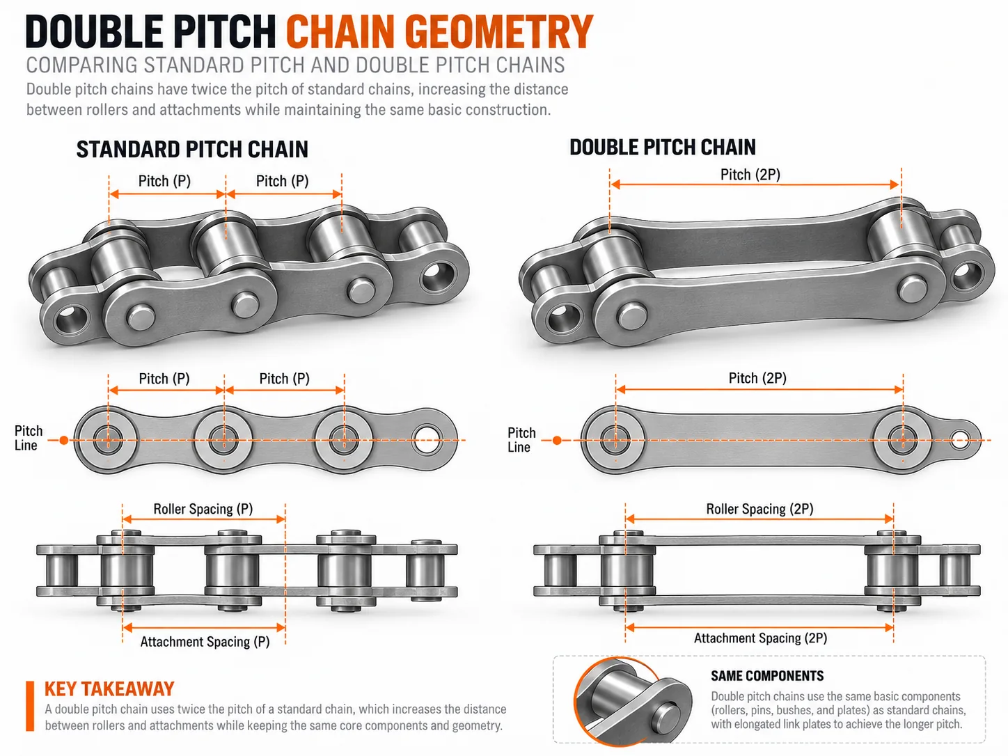
Measure several characteristics before removing the chain. Pitch locates the basic gearing relationship, but inside width, roller or bush diameter, pin diameter, plate height, overall width and attachment dimensions distinguish configurations that can share the same nominal pitch.
For a worn strand, measure cumulative pitch across multiple links. Photograph the chain from the side and end, and include the sprocket where practical.
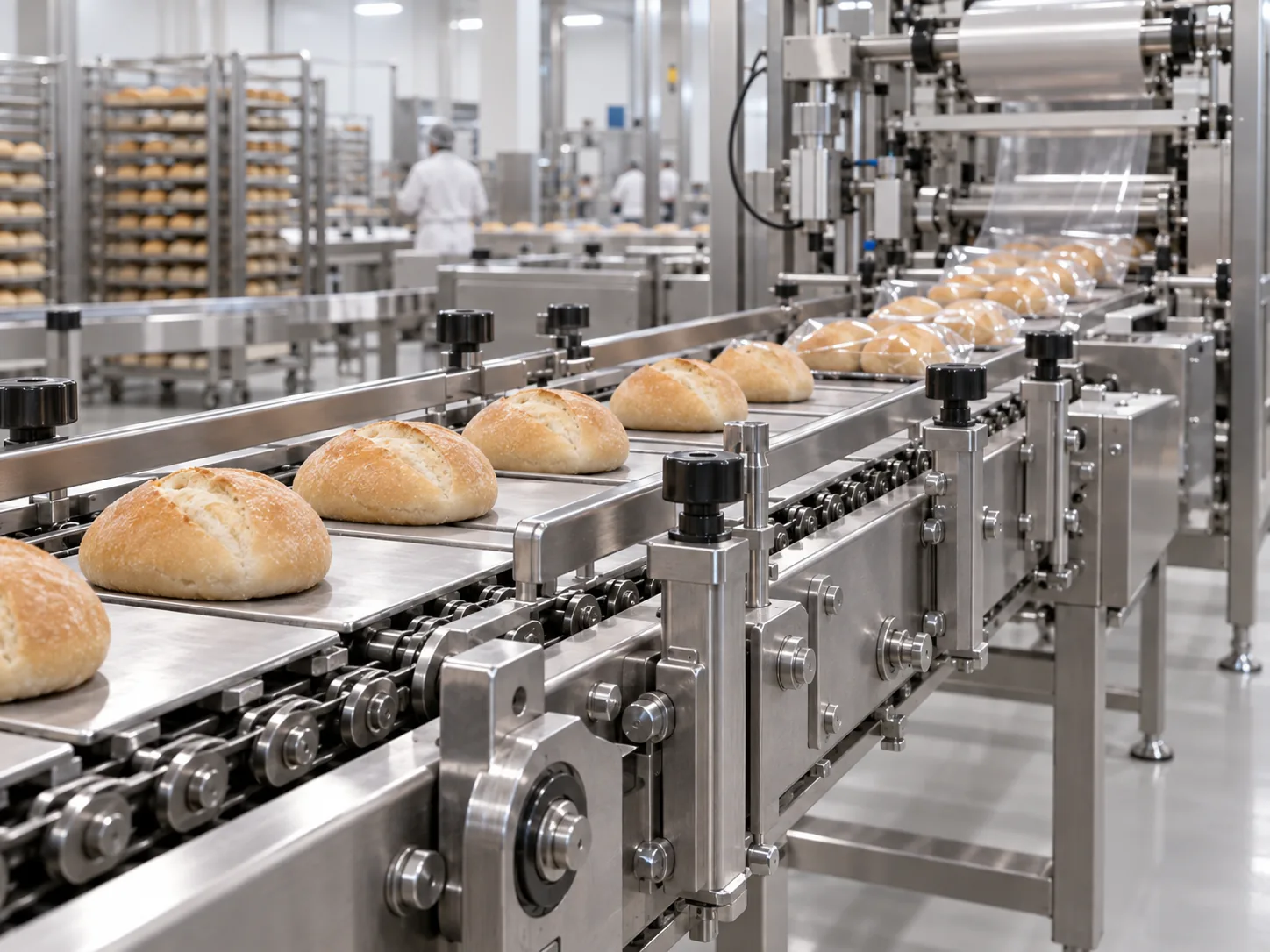
The same chain geometry can behave differently in a humid proofer, a hot oven, an ambient cooling section or a washdown area. For how to inspect chain and sprocket wear, document the exact machine zone, whether the chain carries product directly or moves pans/fixtures, and whether the joint sees heat, moisture, cleaning chemicals or abrasive residue.
Process data helps determine which characteristics are fixed by interchangeability and which characteristics—such as material, clearance or attachment manufacturing method—should be reviewed for the application.
A chain does not operate independently. Rollers or bushes must enter and leave the sprocket tooth spaces smoothly, while guide tracks support the strand without forcing it sideways. Hooked teeth, shaft misalignment, eccentric sprockets or a tight guide can make a new chain wear quickly.
Inspect the complete path through one full circuit. If damage repeats at the same machine location, investigate the local support, transfer or carrier before assuming the chain itself is defective.
Pitch, width, roller/bush, pin, plate, overall width and attachment pattern.
Temperature, moisture, washdown, speed, load, production hours and starts.
Sprockets, guides, chain centers, take-up, alignment and carrier clearances.
Approve the final ordered geometry, material and application-dependent configuration before installation.
Ask what changed before the problem appeared: production rate, product or pan weight, cleaning cycle, lubricant, temperature, maintenance interval or replaced sprockets. Trend information is more valuable than a single photograph because it shows whether wear is uniform or concentrated.
During routine inspection, look for stiff joints, roller wear, pin movement, cracked or bent attachments, abnormal side contact and uneven take-up. Keep guards and safety procedures in place according to the machine owner’s requirements.
Include the measured dimensions, machine/process name, photos, drawing if available, quantity or required chain length, attachment interval, chain-center spacing, sprocket information, temperature, washdown condition, load and target delivery window. Review the przewodnik po wyborze sieci piekarni and the product-family overview for the next decision step.
For an additional allocated product reference, review chain and sprocket options while preparing the sprocket-side details of the RFQ.
A useful diagnosis starts with evidence that can be repeated by a second person. evaluating the chain and sprocket as a mating wear system. Record multi-pitch elongation, roller/bush condition, tooth profile, seating, alignment and take-up position. When the chain is worn, note which readings may be influenced by joint clearance or deformation, and prefer multi-pitch or multi-point measurements over one isolated dimension.
The chain does not operate by itself. In drive and tail sprockets on bakery conveyors, inspect the sprockets, guides, return path, take-up and carrier interface at the same time. The symptom to watch is hooked teeth, irregular seating, pitch growth or vibration at engagement. A local problem that repeats at one machine position often points to alignment, clearance or mating-hardware issues rather than a uniform chain problem.
The practical decision is to compare chain wear and tooth wear together so a new component is not paired with a damaging mate. That prevents a common error: changing chain tension, material or size before the root constraint has been identified. Use the chain drawing and the machine envelope together, because a configuration that looks correct in isolation can still interfere with a guard, transfer plate, sensor bracket or carrier.
Describe the operating cycle rather than a single adjective such as “hot,” “wet” or “food grade.” State normal and peak temperature where relevant, moisture or cleaning exposure, speed, start/stop behavior and lubrication limitations. These details decide whether clearances, materials or maintenance practice need to change while the basic geometry remains fixed.
| Sprawdzać | Dlaczego to ważne | Co wysłać lub zweryfikować |
|---|---|---|
| Identification | Confirm multi-pitch elongation, roller/bush condition, tooth profile, seating, alignment and take-up position. Use a measurement sequence that can be repeated after removal so the installed and bench readings can be compared. | Dimensioned sketch, scale-aware photos and any legacy drawing or part number. |
| Route position | Map where the chain runs through drive and tail sprockets on bakery conveyors. Mark the exact location of hooked teeth, irregular seating, pitch growth or vibration at engagement instead of reporting the condition only as a whole-line problem. | Context photo showing the conveyor section, drive/tail positions and return path. |
| Mating parts | Inspect tooth profile, roller seating, shaft/sprocket alignment, guide contact and take-up reserve. These parts can create wear patterns that imitate a chain-selection problem. | Sprocket tooth count and photos, guide layout and current take-up position. |
| Load path | Identify how product carriers, pans, rods or fixtures transfer load into the chain. For this topic, the key focus is evaluating the chain and sprocket as a mating wear system. | Carrier drawing, attachment interval, chain-center spacing and supported mass/force where known. |
| Środowisko | Record temperature, humidity, washdown, contamination and lubrication restrictions by machine zone. Separate continuous exposure from short peaks or cleaning events. | Operating-condition summary and maintenance/lubrication practice. |
| Release | The final engineering action is to compare chain wear and tooth wear together so a new component is not paired with a damaging mate. The approved drawing should distinguish fixed interchange dimensions from selectable options. | wear measurements, tooth count, photos, chain dimensions, alignment observations and maintenance history. |
A uniform change along the whole strand suggests a different mechanism from damage concentrated at one sprocket, guide or transfer. For How to Inspect Chain and Sprocket Wear, compare left/right sides and loaded/return paths. The distribution of wear can reveal whether the driver is joint wear, side loading, contamination, thermal change or a carrier that is forcing the chain out of its natural path.
Increasing tension can temporarily change noise or tracking without correcting the underlying cause. If the observed issue is hooked teeth, irregular seating, pitch growth or vibration at engagement, first confirm alignment, take-up geometry and articulation. Excessive tension can add bearing load and make a marginal guide or attachment problem worse.
Bakery equipment can move between production, cleaning and shutdown states. A chain may articulate normally when cool and become tight when heated, or run freely during production but corrode after repeated wet shutdowns. Record the state in which the symptom occurs so the selected corrective action addresses the real duty cycle.
For an unknown chain, one close-up is not enough. Pair a complete machine-zone image with side and end views of several pitches, a sprocket-engagement photo and a clear attachment/carrier view. Place a scale only where it does not hide the feature being measured. This photo set makes evaluating the chain and sprocket as a mating wear system easier to evaluate remotely.
Record multi-pitch elongation, roller/bush condition, tooth profile, seating, alignment and take-up position, chain centers, sprocket tooth count and the carrier interface before changing components.
Describe what happens in drive and tail sprockets on bakery conveyors, including temperature or moisture changes, speed, load and cleaning/lubrication constraints.
Document where hooked teeth, irregular seating, pitch growth or vibration at engagement appears. Compare drive, tail, loaded run, return run and transfer points rather than averaging the entire conveyor.
Include wear measurements, tooth count, photos, chain dimensions, alignment observations and maintenance history. State the required quantity or chain length and any documentation needed with the order.
Review pitch, widths, pin/roller geometry, attachments and material notes on one controlled drawing revision. For How to Inspect Chain and Sprocket Wear, the release decision should explicitly address evaluating the chain and sprocket as a mating wear system.
After installation, observe at least one full circuit, check sprocket entry/exit and carrier clearance, and recheck take-up according to the machine maker’s procedure. New chain should not be used to compensate for worn or misaligned hardware.
The main reason to keep this process structured is that evaluating the chain and sprocket as a mating wear system interacts with more than one component. A change that improves one symptom can shift load into another part of the mechanism. For example, correcting guide alignment may reduce side wear but also expose a take-up setting that was previously compensating for the misalignment. Record changes one at a time so the result can be interpreted.
For planned maintenance, compare the present condition with a baseline whenever one exists. If there is no baseline, create one during the next shutdown: photograph the sprockets and guide surfaces, record take-up position, measure a defined number of pitches, and note the chain’s location in drive and tail sprockets on bakery conveyors. Repeating the same observations later is more informative than relying on general statements such as “the chain has stretched.”
When an existing drawing is available, verify that the installed hardware still matches it. Bakery equipment is often modified over its service life: carriers can be repaired, guide rails moved, sprockets replaced, and attachment intervals changed. The drawing remains useful, but field verification prevents a historical document from being treated as proof of the current configuration.
Procurement and engineering should use the same evidence package. The RFQ should not separate commercial quantity from technical context: wear measurements, tooth count, photos, chain dimensions, alignment observations and maintenance history. This makes it possible to judge whether a standard series, a modified attachment or a custom replacement is the appropriate route without creating unnecessary back-and-forth.
Finally, treat the website as a preparation tool rather than the controlling product drawing. Measurements and diagrams narrow the family and help organize the RFQ; the released drawing defines the ordered configuration. That distinction is especially important where hooked teeth, irregular seating, pitch growth or vibration at engagement could have more than one mechanical cause.
Use How to Inspect Chain and Sprocket Wear as a machine-level question, not just a chain inspection. Compare the loaded and return runs, drive and tail ends, and any transfer or carrier transition in drive and tail sprockets on bakery conveyors. Document whether hooked teeth, irregular seating, pitch growth or vibration at engagement is distributed along the strand or repeats at one location. That pattern helps separate progressive joint wear from alignment, guide, sprocket or carrier problems that a new chain alone will not correct.
The working record should include multi-pitch elongation, roller/bush condition, tooth profile, seating, alignment and take-up position. Mark which values are fixed by the existing machine and which values can be changed to improve service. The central engineering focus is evaluating the chain and sprocket as a mating wear system. When a legacy part number conflicts with field measurements, hold the RFQ until the installed interface and the controlled drawing can be reconciled.
A useful enquiry combines commercial quantity with the technical package: wear measurements, tooth count, photos, chain dimensions, alignment observations and maintenance history. Also state whether the request is a direct replacement, a planned modification or a new machine design. The release objective is to compare chain wear and tooth wear together so a new component is not paired with a damaging mate. This reduces quote revisions and prevents a visually similar chain from being treated as interchangeable before geometry and duty have been checked.
Use the old reference if available, but verify the installed geometry and duty. Machine modifications, previous substitutions or wear can make a part number alone incomplete.
Use a multi-pitch measurement across a practical number of links and record the method. Compare it with the nominal pitch and machine maintenance limits rather than relying on one adjacent-link measurement.
Whenever tooth wear, hooking, alignment concerns or repeated premature chain wear are present. The chain and sprocket work as a meshing system.
Bakery Chain Technical Guide
Why Bakery Chains Develop Stiff Joints is best answered by combining measured chain geometry, machine duty and the operating environment. This guide shows what to inspect, record and discuss before a replacement or new-chain decision.
Why Bakery Chains Develop Stiff Joints should be evaluated from the actual conveyor. Start with chain pitch, transverse geometry, sprocket condition and any carrier attachment, then add temperature, moisture, washdown, load, speed and take-up information. The objective is not to identify a chain by appearance; it is to produce an RFQ that preserves the machine interface and makes application-dependent choices explicit.
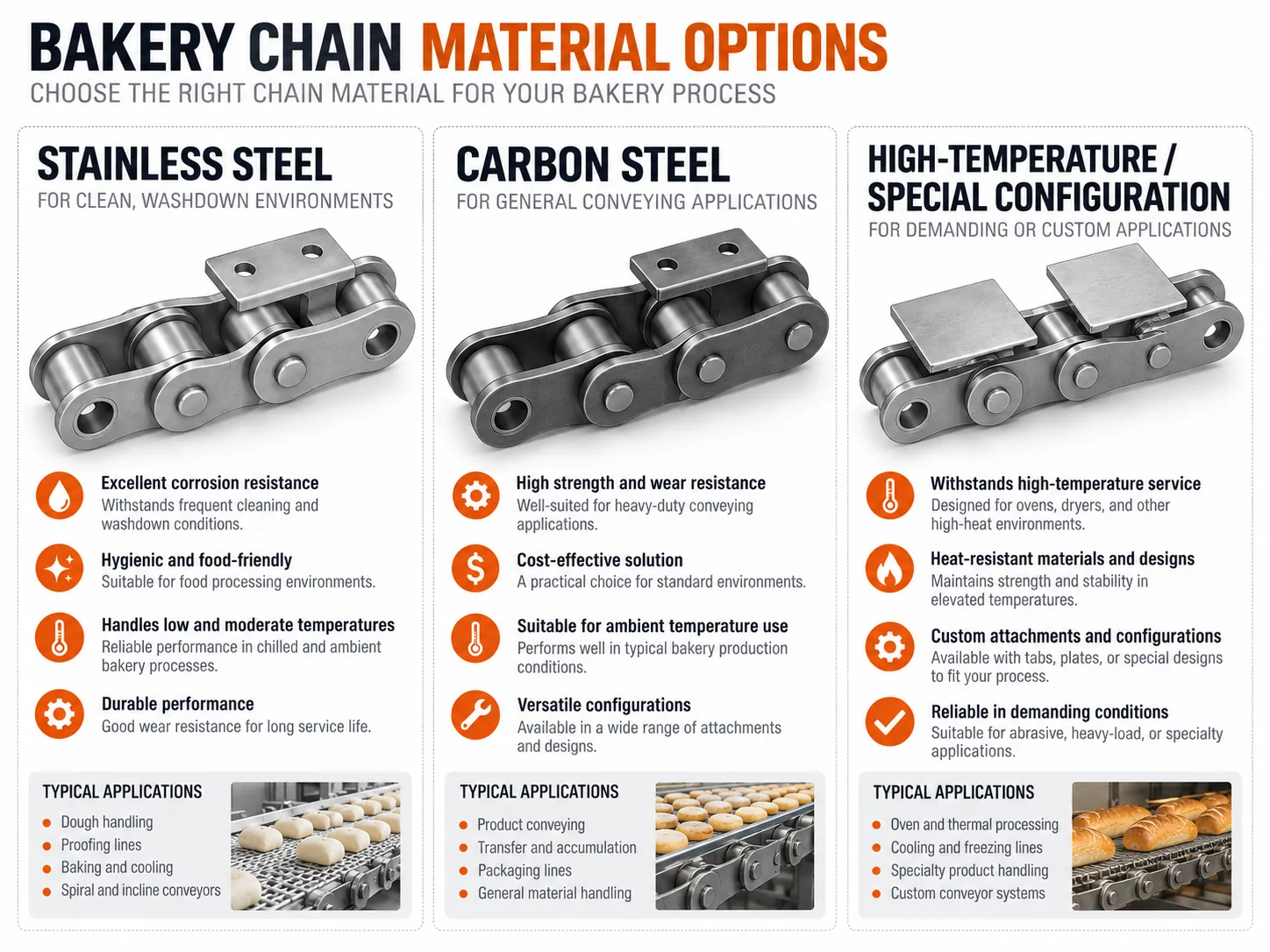
Measure several characteristics before removing the chain. Pitch locates the basic gearing relationship, but inside width, roller or bush diameter, pin diameter, plate height, overall width and attachment dimensions distinguish configurations that can share the same nominal pitch.
For a worn strand, measure cumulative pitch across multiple links. Photograph the chain from the side and end, and include the sprocket where practical.
The same chain geometry can behave differently in a humid proofer, a hot oven, an ambient cooling section or a washdown area. For why bakery chains develop stiff joints, document the exact machine zone, whether the chain carries product directly or moves pans/fixtures, and whether the joint sees heat, moisture, cleaning chemicals or abrasive residue.
Process data helps determine which characteristics are fixed by interchangeability and which characteristics—such as material, clearance or attachment manufacturing method—should be reviewed for the application.
A chain does not operate independently. Rollers or bushes must enter and leave the sprocket tooth spaces smoothly, while guide tracks support the strand without forcing it sideways. Hooked teeth, shaft misalignment, eccentric sprockets or a tight guide can make a new chain wear quickly.
Inspect the complete path through one full circuit. If damage repeats at the same machine location, investigate the local support, transfer or carrier before assuming the chain itself is defective.
Pitch, width, roller/bush, pin, plate, overall width and attachment pattern.
Temperature, moisture, washdown, speed, load, production hours and starts.
Sprockets, guides, chain centers, take-up, alignment and carrier clearances.
Approve the final ordered geometry, material and application-dependent configuration before installation.
Ask what changed before the problem appeared: production rate, product or pan weight, cleaning cycle, lubricant, temperature, maintenance interval or replaced sprockets. Trend information is more valuable than a single photograph because it shows whether wear is uniform or concentrated.
During routine inspection, look for stiff joints, roller wear, pin movement, cracked or bent attachments, abnormal side contact and uneven take-up. Keep guards and safety procedures in place according to the machine owner’s requirements.
Include the measured dimensions, machine/process name, photos, drawing if available, quantity or required chain length, attachment interval, chain-center spacing, sprocket information, temperature, washdown condition, load and target delivery window. Review the przewodnik po wyborze sieci piekarni and the product-family overview for the next decision step.
A useful diagnosis starts with evidence that can be repeated by a second person. finding why articulation resistance develops at specific joints or machine zones. Record joint freedom, pin/bush wear, contamination, corrosion, lubrication access and side loading. When the chain is worn, note which readings may be influenced by joint clearance or deformation, and prefer multi-pitch or multi-point measurements over one isolated dimension.
The chain does not operate by itself. In proofing, oven, cooling and transfer conveyors, inspect the sprockets, guides, return path, take-up and carrier interface at the same time. The symptom to watch is links that do not articulate freely through sprockets or return bends. A local problem that repeats at one machine position often points to alignment, clearance or mating-hardware issues rather than a uniform chain problem.
The practical decision is to identify whether stiffness is caused by contamination, corrosion, deformation, clearance loss or lubrication before adjusting tension. That prevents a common error: changing chain tension, material or size before the root constraint has been identified. Use the chain drawing and the machine envelope together, because a configuration that looks correct in isolation can still interfere with a guard, transfer plate, sensor bracket or carrier.
Describe the operating cycle rather than a single adjective such as “hot,” “wet” or “food grade.” State normal and peak temperature where relevant, moisture or cleaning exposure, speed, start/stop behavior and lubrication limitations. These details decide whether clearances, materials or maintenance practice need to change while the basic geometry remains fixed.
| Sprawdzać | Dlaczego to ważne | Co wysłać lub zweryfikować |
|---|---|---|
| Identification | Confirm joint freedom, pin/bush wear, contamination, corrosion, lubrication access and side loading. Use a measurement sequence that can be repeated after removal so the installed and bench readings can be compared. | Dimensioned sketch, scale-aware photos and any legacy drawing or part number. |
| Route position | Map where the chain runs through proofing, oven, cooling and transfer conveyors. Mark the exact location of links that do not articulate freely through sprockets or return bends instead of reporting the condition only as a whole-line problem. | Context photo showing the conveyor section, drive/tail positions and return path. |
| Mating parts | Inspect tooth profile, roller seating, shaft/sprocket alignment, guide contact and take-up reserve. These parts can create wear patterns that imitate a chain-selection problem. | Sprocket tooth count and photos, guide layout and current take-up position. |
| Load path | Identify how product carriers, pans, rods or fixtures transfer load into the chain. For this topic, the key focus is finding why articulation resistance develops at specific joints or machine zones. | Carrier drawing, attachment interval, chain-center spacing and supported mass/force where known. |
| Środowisko | Record temperature, humidity, washdown, contamination and lubrication restrictions by machine zone. Separate continuous exposure from short peaks or cleaning events. | Operating-condition summary and maintenance/lubrication practice. |
| Release | The final engineering action is to identify whether stiffness is caused by contamination, corrosion, deformation, clearance loss or lubrication before adjusting tension. The approved drawing should distinguish fixed interchange dimensions from selectable options. | photos/video of stiff zone, environment, lubrication, chain geometry and service history. |
A uniform change along the whole strand suggests a different mechanism from damage concentrated at one sprocket, guide or transfer. For Why Bakery Chains Develop Stiff Joints, compare left/right sides and loaded/return paths. The distribution of wear can reveal whether the driver is joint wear, side loading, contamination, thermal change or a carrier that is forcing the chain out of its natural path.
Increasing tension can temporarily change noise or tracking without correcting the underlying cause. If the observed issue is links that do not articulate freely through sprockets or return bends, first confirm alignment, take-up geometry and articulation. Excessive tension can add bearing load and make a marginal guide or attachment problem worse.
Bakery equipment can move between production, cleaning and shutdown states. A chain may articulate normally when cool and become tight when heated, or run freely during production but corrode after repeated wet shutdowns. Record the state in which the symptom occurs so the selected corrective action addresses the real duty cycle.
For an unknown chain, one close-up is not enough. Pair a complete machine-zone image with side and end views of several pitches, a sprocket-engagement photo and a clear attachment/carrier view. Place a scale only where it does not hide the feature being measured. This photo set makes finding why articulation resistance develops at specific joints or machine zones easier to evaluate remotely.
Record joint freedom, pin/bush wear, contamination, corrosion, lubrication access and side loading, chain centers, sprocket tooth count and the carrier interface before changing components.
Describe what happens in proofing, oven, cooling and transfer conveyors, including temperature or moisture changes, speed, load and cleaning/lubrication constraints.
Document where links that do not articulate freely through sprockets or return bends appears. Compare drive, tail, loaded run, return run and transfer points rather than averaging the entire conveyor.
Include photos/video of stiff zone, environment, lubrication, chain geometry and service history. State the required quantity or chain length and any documentation needed with the order.
Review pitch, widths, pin/roller geometry, attachments and material notes on one controlled drawing revision. For Why Bakery Chains Develop Stiff Joints, the release decision should explicitly address finding why articulation resistance develops at specific joints or machine zones.
After installation, observe at least one full circuit, check sprocket entry/exit and carrier clearance, and recheck take-up according to the machine maker’s procedure. New chain should not be used to compensate for worn or misaligned hardware.
The main reason to keep this process structured is that finding why articulation resistance develops at specific joints or machine zones interacts with more than one component. A change that improves one symptom can shift load into another part of the mechanism. For example, correcting guide alignment may reduce side wear but also expose a take-up setting that was previously compensating for the misalignment. Record changes one at a time so the result can be interpreted.
For planned maintenance, compare the present condition with a baseline whenever one exists. If there is no baseline, create one during the next shutdown: photograph the sprockets and guide surfaces, record take-up position, measure a defined number of pitches, and note the chain’s location in proofing, oven, cooling and transfer conveyors. Repeating the same observations later is more informative than relying on general statements such as “the chain has stretched.”
When an existing drawing is available, verify that the installed hardware still matches it. Bakery equipment is often modified over its service life: carriers can be repaired, guide rails moved, sprockets replaced, and attachment intervals changed. The drawing remains useful, but field verification prevents a historical document from being treated as proof of the current configuration.
Procurement and engineering should use the same evidence package. The RFQ should not separate commercial quantity from technical context: photos/video of stiff zone, environment, lubrication, chain geometry and service history. This makes it possible to judge whether a standard series, a modified attachment or a custom replacement is the appropriate route without creating unnecessary back-and-forth.
Finally, treat the website as a preparation tool rather than the controlling product drawing. Measurements and diagrams narrow the family and help organize the RFQ; the released drawing defines the ordered configuration. That distinction is especially important where links that do not articulate freely through sprockets or return bends could have more than one mechanical cause.
Use Why Bakery Chains Develop Stiff Joints as a machine-level question, not just a chain inspection. Compare the loaded and return runs, drive and tail ends, and any transfer or carrier transition in proofing, oven, cooling and transfer conveyors. Document whether links that do not articulate freely through sprockets or return bends is distributed along the strand or repeats at one location. That pattern helps separate progressive joint wear from alignment, guide, sprocket or carrier problems that a new chain alone will not correct.
The working record should include joint freedom, pin/bush wear, contamination, corrosion, lubrication access and side loading. Mark which values are fixed by the existing machine and which values can be changed to improve service. The central engineering focus is finding why articulation resistance develops at specific joints or machine zones. When a legacy part number conflicts with field measurements, hold the RFQ until the installed interface and the controlled drawing can be reconciled.
A useful enquiry combines commercial quantity with the technical package: photos/video of stiff zone, environment, lubrication, chain geometry and service history. Also state whether the request is a direct replacement, a planned modification or a new machine design. The release objective is to identify whether stiffness is caused by contamination, corrosion, deformation, clearance loss or lubrication before adjusting tension. This reduces quote revisions and prevents a visually similar chain from being treated as interchangeable before geometry and duty have been checked.
Use the old reference if available, but verify the installed geometry and duty. Machine modifications, previous substitutions or wear can make a part number alone incomplete.
Use a multi-pitch measurement across a practical number of links and record the method. Compare it with the nominal pitch and machine maintenance limits rather than relying on one adjacent-link measurement.
Whenever tooth wear, hooking, alignment concerns or repeated premature chain wear are present. The chain and sprocket work as a meshing system.
Bakery Chain Technical Guide
Material Selection for Bakery Conveyor Components is best answered by combining measured chain geometry, machine duty and the operating environment. This guide shows what to inspect, record and discuss before a replacement or new-chain decision.
Material Selection for Bakery Conveyor Components should be evaluated from the actual conveyor. Start with chain pitch, transverse geometry, sprocket condition and any carrier attachment, then add temperature, moisture, washdown, load, speed and take-up information. The objective is not to identify a chain by appearance; it is to produce an RFQ that preserves the machine interface and makes application-dependent choices explicit.
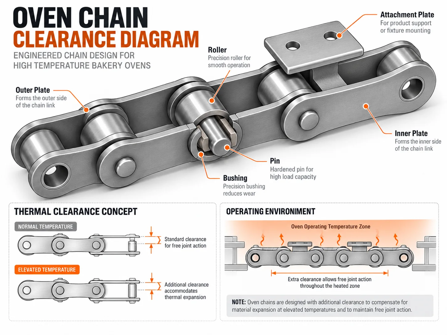
Measure several characteristics before removing the chain. Pitch locates the basic gearing relationship, but inside width, roller or bush diameter, pin diameter, plate height, overall width and attachment dimensions distinguish configurations that can share the same nominal pitch.
For a worn strand, measure cumulative pitch across multiple links. Photograph the chain from the side and end, and include the sprocket where practical.
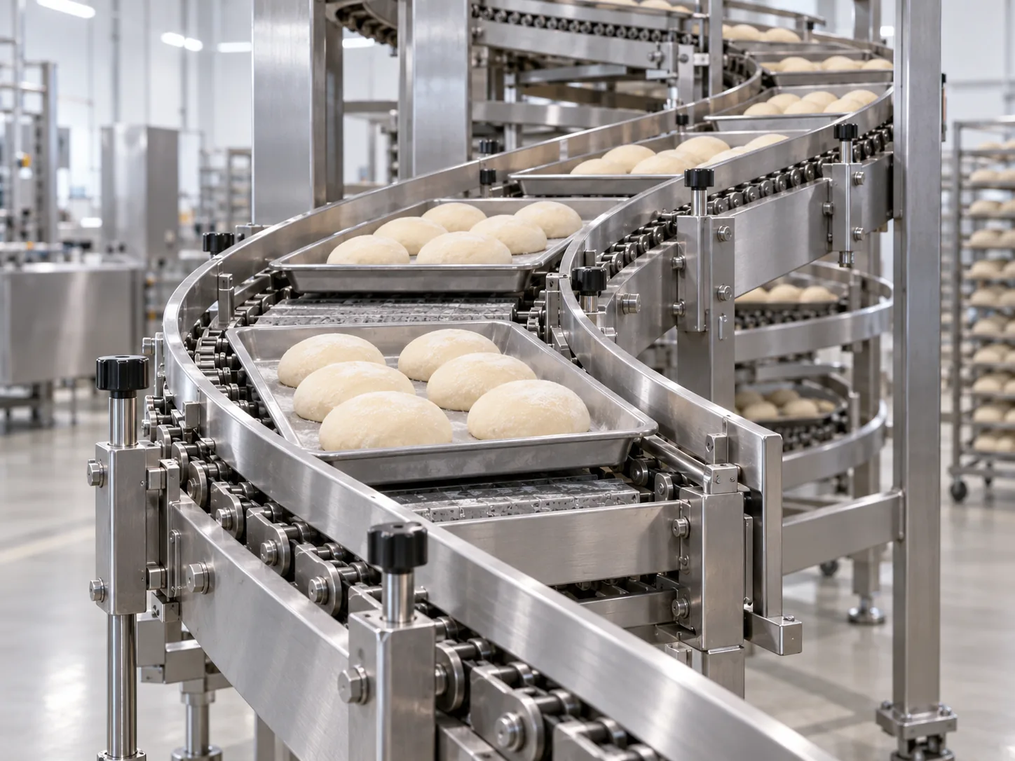
The same chain geometry can behave differently in a humid proofer, a hot oven, an ambient cooling section or a washdown area. For material selection for bakery conveyor components, document the exact machine zone, whether the chain carries product directly or moves pans/fixtures, and whether the joint sees heat, moisture, cleaning chemicals or abrasive residue.
Process data helps determine which characteristics are fixed by interchangeability and which characteristics—such as material, clearance or attachment manufacturing method—should be reviewed for the application.
A chain does not operate independently. Rollers or bushes must enter and leave the sprocket tooth spaces smoothly, while guide tracks support the strand without forcing it sideways. Hooked teeth, shaft misalignment, eccentric sprockets or a tight guide can make a new chain wear quickly.
Inspect the complete path through one full circuit. If damage repeats at the same machine location, investigate the local support, transfer or carrier before assuming the chain itself is defective.
Pitch, width, roller/bush, pin, plate, overall width and attachment pattern.
Temperature, moisture, washdown, speed, load, production hours and starts.
Sprockets, guides, chain centers, take-up, alignment and carrier clearances.
Approve the final ordered geometry, material and application-dependent configuration before installation.
Ask what changed before the problem appeared: production rate, product or pan weight, cleaning cycle, lubricant, temperature, maintenance interval or replaced sprockets. Trend information is more valuable than a single photograph because it shows whether wear is uniform or concentrated.
During routine inspection, look for stiff joints, roller wear, pin movement, cracked or bent attachments, abnormal side contact and uneven take-up. Keep guards and safety procedures in place according to the machine owner’s requirements.
Include the measured dimensions, machine/process name, photos, drawing if available, quantity or required chain length, attachment interval, chain-center spacing, sprocket information, temperature, washdown condition, load and target delivery window. Review the przewodnik po wyborze sieci piekarni and the product-family overview for the next decision step.
A useful diagnosis starts with evidence that can be repeated by a second person. matching material to the function of pins, bushes, rollers, plates, attachments and surrounding guides. Record contact stress, sliding/rolling wear, temperature, corrosion exposure, geometry and maintenance. When the chain is worn, note which readings may be influenced by joint clearance or deformation, and prefer multi-pitch or multi-point measurements over one isolated dimension.
The chain does not operate by itself. In bakery conveyors with mixed mechanical and environmental demands, inspect the sprockets, guides, return path, take-up and carrier interface at the same time. The symptom to watch is one material choice solving corrosion but creating wear or galling elsewhere. A local problem that repeats at one machine position often points to alignment, clearance or mating-hardware issues rather than a uniform chain problem.
The practical decision is to evaluate each component interface and its failure mode instead of specifying a single material generically. That prevents a common error: changing chain tension, material or size before the root constraint has been identified. Use the chain drawing and the machine envelope together, because a configuration that looks correct in isolation can still interfere with a guard, transfer plate, sensor bracket or carrier.
Describe the operating cycle rather than a single adjective such as “hot,” “wet” or “food grade.” State normal and peak temperature where relevant, moisture or cleaning exposure, speed, start/stop behavior and lubrication limitations. These details decide whether clearances, materials or maintenance practice need to change while the basic geometry remains fixed.
| Sprawdzać | Dlaczego to ważne | Co wysłać lub zweryfikować |
|---|---|---|
| Identification | Confirm contact stress, sliding/rolling wear, temperature, corrosion exposure, geometry and maintenance. Use a measurement sequence that can be repeated after removal so the installed and bench readings can be compared. | Dimensioned sketch, scale-aware photos and any legacy drawing or part number. |
| Route position | Map where the chain runs through bakery conveyors with mixed mechanical and environmental demands. Mark the exact location of one material choice solving corrosion but creating wear or galling elsewhere instead of reporting the condition only as a whole-line problem. | Context photo showing the conveyor section, drive/tail positions and return path. |
| Mating parts | Inspect tooth profile, roller seating, shaft/sprocket alignment, guide contact and take-up reserve. These parts can create wear patterns that imitate a chain-selection problem. | Sprocket tooth count and photos, guide layout and current take-up position. |
| Load path | Identify how product carriers, pans, rods or fixtures transfer load into the chain. For this topic, the key focus is matching material to the function of pins, bushes, rollers, plates, attachments and surrounding guides. | Carrier drawing, attachment interval, chain-center spacing and supported mass/force where known. |
| Środowisko | Record temperature, humidity, washdown, contamination and lubrication restrictions by machine zone. Separate continuous exposure from short peaks or cleaning events. | Operating-condition summary and maintenance/lubrication practice. |
| Release | The final engineering action is to evaluate each component interface and its failure mode instead of specifying a single material generically. The approved drawing should distinguish fixed interchange dimensions from selectable options. | component function, duty, environment, drawing and required material documentation. |
A uniform change along the whole strand suggests a different mechanism from damage concentrated at one sprocket, guide or transfer. For Material Selection for Bakery Conveyor Components, compare left/right sides and loaded/return paths. The distribution of wear can reveal whether the driver is joint wear, side loading, contamination, thermal change or a carrier that is forcing the chain out of its natural path.
Increasing tension can temporarily change noise or tracking without correcting the underlying cause. If the observed issue is one material choice solving corrosion but creating wear or galling elsewhere, first confirm alignment, take-up geometry and articulation. Excessive tension can add bearing load and make a marginal guide or attachment problem worse.
Bakery equipment can move between production, cleaning and shutdown states. A chain may articulate normally when cool and become tight when heated, or run freely during production but corrode after repeated wet shutdowns. Record the state in which the symptom occurs so the selected corrective action addresses the real duty cycle.
For an unknown chain, one close-up is not enough. Pair a complete machine-zone image with side and end views of several pitches, a sprocket-engagement photo and a clear attachment/carrier view. Place a scale only where it does not hide the feature being measured. This photo set makes matching material to the function of pins, bushes, rollers, plates, attachments and surrounding guides easier to evaluate remotely.
Record contact stress, sliding/rolling wear, temperature, corrosion exposure, geometry and maintenance, chain centers, sprocket tooth count and the carrier interface before changing components.
Describe what happens in bakery conveyors with mixed mechanical and environmental demands, including temperature or moisture changes, speed, load and cleaning/lubrication constraints.
Document where one material choice solving corrosion but creating wear or galling elsewhere appears. Compare drive, tail, loaded run, return run and transfer points rather than averaging the entire conveyor.
Include component function, duty, environment, drawing and required material documentation. State the required quantity or chain length and any documentation needed with the order.
Review pitch, widths, pin/roller geometry, attachments and material notes on one controlled drawing revision. For Material Selection for Bakery Conveyor Components, the release decision should explicitly address matching material to the function of pins, bushes, rollers, plates, attachments and surrounding guides.
After installation, observe at least one full circuit, check sprocket entry/exit and carrier clearance, and recheck take-up according to the machine maker’s procedure. New chain should not be used to compensate for worn or misaligned hardware.
The main reason to keep this process structured is that matching material to the function of pins, bushes, rollers, plates, attachments and surrounding guides interacts with more than one component. A change that improves one symptom can shift load into another part of the mechanism. For example, correcting guide alignment may reduce side wear but also expose a take-up setting that was previously compensating for the misalignment. Record changes one at a time so the result can be interpreted.
For planned maintenance, compare the present condition with a baseline whenever one exists. If there is no baseline, create one during the next shutdown: photograph the sprockets and guide surfaces, record take-up position, measure a defined number of pitches, and note the chain’s location in bakery conveyors with mixed mechanical and environmental demands. Repeating the same observations later is more informative than relying on general statements such as “the chain has stretched.”
When an existing drawing is available, verify that the installed hardware still matches it. Bakery equipment is often modified over its service life: carriers can be repaired, guide rails moved, sprockets replaced, and attachment intervals changed. The drawing remains useful, but field verification prevents a historical document from being treated as proof of the current configuration.
Procurement and engineering should use the same evidence package. The RFQ should not separate commercial quantity from technical context: component function, duty, environment, drawing and required material documentation. This makes it possible to judge whether a standard series, a modified attachment or a custom replacement is the appropriate route without creating unnecessary back-and-forth.
Finally, treat the website as a preparation tool rather than the controlling product drawing. Measurements and diagrams narrow the family and help organize the RFQ; the released drawing defines the ordered configuration. That distinction is especially important where one material choice solving corrosion but creating wear or galling elsewhere could have more than one mechanical cause.
Use Material Selection for Bakery Conveyor Components as a machine-level question, not just a chain inspection. Compare the loaded and return runs, drive and tail ends, and any transfer or carrier transition in bakery conveyors with mixed mechanical and environmental demands. Document whether one material choice solving corrosion but creating wear or galling elsewhere is distributed along the strand or repeats at one location. That pattern helps separate progressive joint wear from alignment, guide, sprocket or carrier problems that a new chain alone will not correct.
The working record should include contact stress, sliding/rolling wear, temperature, corrosion exposure, geometry and maintenance. Mark which values are fixed by the existing machine and which values can be changed to improve service. The central engineering focus is matching material to the function of pins, bushes, rollers, plates, attachments and surrounding guides. When a legacy part number conflicts with field measurements, hold the RFQ until the installed interface and the controlled drawing can be reconciled.
A useful enquiry combines commercial quantity with the technical package: component function, duty, environment, drawing and required material documentation. Also state whether the request is a direct replacement, a planned modification or a new machine design. The release objective is to evaluate each component interface and its failure mode instead of specifying a single material generically. This reduces quote revisions and prevents a visually similar chain from being treated as interchangeable before geometry and duty have been checked.
Use the old reference if available, but verify the installed geometry and duty. Machine modifications, previous substitutions or wear can make a part number alone incomplete.
Use a multi-pitch measurement across a practical number of links and record the method. Compare it with the nominal pitch and machine maintenance limits rather than relying on one adjacent-link measurement.
Whenever tooth wear, hooking, alignment concerns or repeated premature chain wear are present. The chain and sprocket work as a meshing system.
Bakery Chain Technical Guide
Chain Design for Frequent Cleaning is best answered by combining measured chain geometry, machine duty and the operating environment. This guide shows what to inspect, record and discuss before a replacement or new-chain decision.
Chain Design for Frequent Cleaning should be evaluated from the actual conveyor. Start with chain pitch, transverse geometry, sprocket condition and any carrier attachment, then add temperature, moisture, washdown, load, speed and take-up information. The objective is not to identify a chain by appearance; it is to produce an RFQ that preserves the machine interface and makes application-dependent choices explicit.
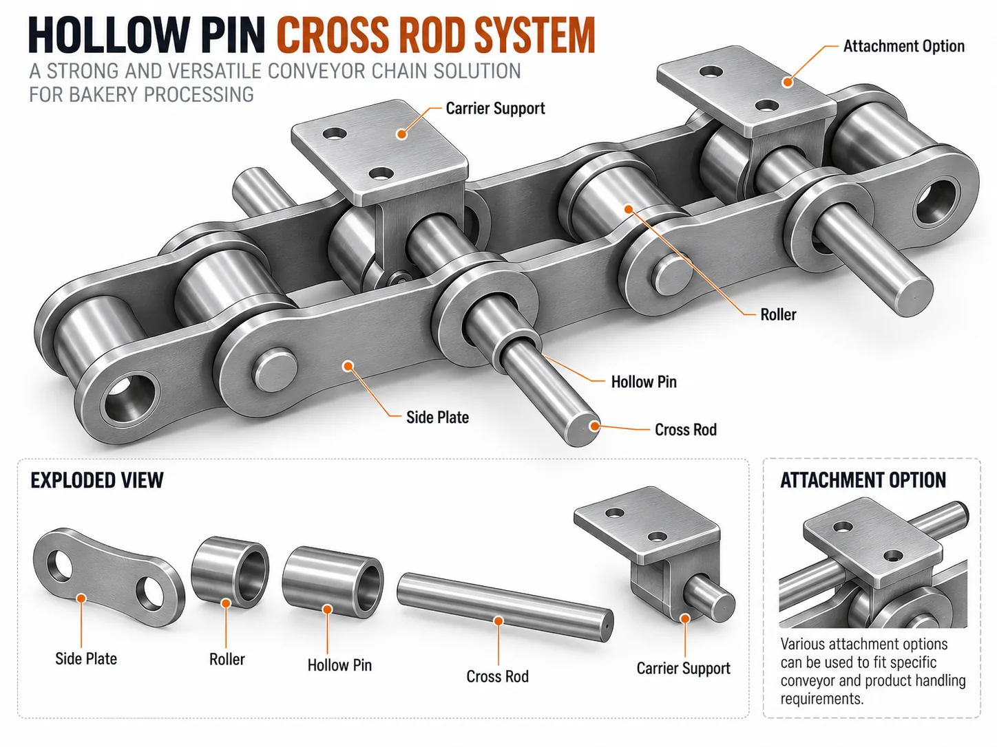
Measure several characteristics before removing the chain. Pitch locates the basic gearing relationship, but inside width, roller or bush diameter, pin diameter, plate height, overall width and attachment dimensions distinguish configurations that can share the same nominal pitch.
For a worn strand, measure cumulative pitch across multiple links. Photograph the chain from the side and end, and include the sprocket where practical.
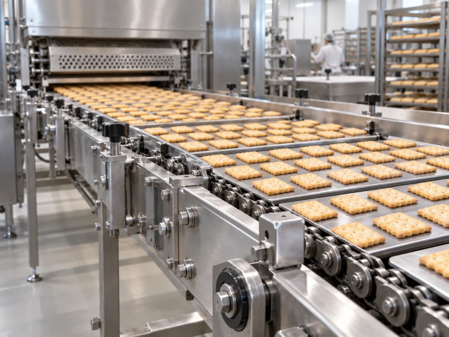
The same chain geometry can behave differently in a humid proofer, a hot oven, an ambient cooling section or a washdown area. For chain design for frequent cleaning, document the exact machine zone, whether the chain carries product directly or moves pans/fixtures, and whether the joint sees heat, moisture, cleaning chemicals or abrasive residue.
Process data helps determine which characteristics are fixed by interchangeability and which characteristics—such as material, clearance or attachment manufacturing method—should be reviewed for the application.
A chain does not operate independently. Rollers or bushes must enter and leave the sprocket tooth spaces smoothly, while guide tracks support the strand without forcing it sideways. Hooked teeth, shaft misalignment, eccentric sprockets or a tight guide can make a new chain wear quickly.
Inspect the complete path through one full circuit. If damage repeats at the same machine location, investigate the local support, transfer or carrier before assuming the chain itself is defective.
Pitch, width, roller/bush, pin, plate, overall width and attachment pattern.
Temperature, moisture, washdown, speed, load, production hours and starts.
Sprockets, guides, chain centers, take-up, alignment and carrier clearances.
Approve the final ordered geometry, material and application-dependent configuration before installation.
Ask what changed before the problem appeared: production rate, product or pan weight, cleaning cycle, lubricant, temperature, maintenance interval or replaced sprockets. Trend information is more valuable than a single photograph because it shows whether wear is uniform or concentrated.
During routine inspection, look for stiff joints, roller wear, pin movement, cracked or bent attachments, abnormal side contact and uneven take-up. Keep guards and safety procedures in place according to the machine owner’s requirements.
Include the measured dimensions, machine/process name, photos, drawing if available, quantity or required chain length, attachment interval, chain-center spacing, sprocket information, temperature, washdown condition, load and target delivery window. Review the przewodnik po wyborze sieci piekarni and the product-family overview for the next decision step.
A useful diagnosis starts with evidence that can be repeated by a second person. designing the chain and carrier interface so cleaning access does not undermine joint performance. Record cleaning frequency, spray direction, chemistry, drainage path, joint exposure and re-lubrication practice. When the chain is worn, note which readings may be influenced by joint clearance or deformation, and prefer multi-pitch or multi-point measurements over one isolated dimension.
The chain does not operate by itself. In sanitary bakery transfer and washdown conveyors, inspect the sprockets, guides, return path, take-up and carrier interface at the same time. The symptom to watch is trapped residue, corrosion pockets, washed-out lubricant or slow drying. A local problem that repeats at one machine position often points to alignment, clearance or mating-hardware issues rather than a uniform chain problem.
The practical decision is to review cleanability, drainage and lubrication recovery as part of the original chain specification. That prevents a common error: changing chain tension, material or size before the root constraint has been identified. Use the chain drawing and the machine envelope together, because a configuration that looks correct in isolation can still interfere with a guard, transfer plate, sensor bracket or carrier.
Describe the operating cycle rather than a single adjective such as “hot,” “wet” or “food grade.” State normal and peak temperature where relevant, moisture or cleaning exposure, speed, start/stop behavior and lubrication limitations. These details decide whether clearances, materials or maintenance practice need to change while the basic geometry remains fixed.
| Sprawdzać | Dlaczego to ważne | Co wysłać lub zweryfikować |
|---|---|---|
| Identification | Confirm cleaning frequency, spray direction, chemistry, drainage path, joint exposure and re-lubrication practice. Use a measurement sequence that can be repeated after removal so the installed and bench readings can be compared. | Dimensioned sketch, scale-aware photos and any legacy drawing or part number. |
| Route position | Map where the chain runs through sanitary bakery transfer and washdown conveyors. Mark the exact location of trapped residue, corrosion pockets, washed-out lubricant or slow drying instead of reporting the condition only as a whole-line problem. | Context photo showing the conveyor section, drive/tail positions and return path. |
| Mating parts | Inspect tooth profile, roller seating, shaft/sprocket alignment, guide contact and take-up reserve. These parts can create wear patterns that imitate a chain-selection problem. | Sprocket tooth count and photos, guide layout and current take-up position. |
| Load path | Identify how product carriers, pans, rods or fixtures transfer load into the chain. For this topic, the key focus is designing the chain and carrier interface so cleaning access does not undermine joint performance. | Carrier drawing, attachment interval, chain-center spacing and supported mass/force where known. |
| Środowisko | Record temperature, humidity, washdown, contamination and lubrication restrictions by machine zone. Separate continuous exposure from short peaks or cleaning events. | Operating-condition summary and maintenance/lubrication practice. |
| Release | The final engineering action is to review cleanability, drainage and lubrication recovery as part of the original chain specification. The approved drawing should distinguish fixed interchange dimensions from selectable options. | cleaning SOP summary, chain geometry, materials, lubrication restrictions and photos. |
A uniform change along the whole strand suggests a different mechanism from damage concentrated at one sprocket, guide or transfer. For Chain Design for Frequent Cleaning, compare left/right sides and loaded/return paths. The distribution of wear can reveal whether the driver is joint wear, side loading, contamination, thermal change or a carrier that is forcing the chain out of its natural path.
Increasing tension can temporarily change noise or tracking without correcting the underlying cause. If the observed issue is trapped residue, corrosion pockets, washed-out lubricant or slow drying, first confirm alignment, take-up geometry and articulation. Excessive tension can add bearing load and make a marginal guide or attachment problem worse.
Bakery equipment can move between production, cleaning and shutdown states. A chain may articulate normally when cool and become tight when heated, or run freely during production but corrode after repeated wet shutdowns. Record the state in which the symptom occurs so the selected corrective action addresses the real duty cycle.
For an unknown chain, one close-up is not enough. Pair a complete machine-zone image with side and end views of several pitches, a sprocket-engagement photo and a clear attachment/carrier view. Place a scale only where it does not hide the feature being measured. This photo set makes designing the chain and carrier interface so cleaning access does not undermine joint performance easier to evaluate remotely.
Record cleaning frequency, spray direction, chemistry, drainage path, joint exposure and re-lubrication practice, chain centers, sprocket tooth count and the carrier interface before changing components.
Describe what happens in sanitary bakery transfer and washdown conveyors, including temperature or moisture changes, speed, load and cleaning/lubrication constraints.
Document where trapped residue, corrosion pockets, washed-out lubricant or slow drying appears. Compare drive, tail, loaded run, return run and transfer points rather than averaging the entire conveyor.
Include cleaning SOP summary, chain geometry, materials, lubrication restrictions and photos. State the required quantity or chain length and any documentation needed with the order.
Review pitch, widths, pin/roller geometry, attachments and material notes on one controlled drawing revision. For Chain Design for Frequent Cleaning, the release decision should explicitly address designing the chain and carrier interface so cleaning access does not undermine joint performance.
After installation, observe at least one full circuit, check sprocket entry/exit and carrier clearance, and recheck take-up according to the machine maker’s procedure. New chain should not be used to compensate for worn or misaligned hardware.
The main reason to keep this process structured is that designing the chain and carrier interface so cleaning access does not undermine joint performance interacts with more than one component. A change that improves one symptom can shift load into another part of the mechanism. For example, correcting guide alignment may reduce side wear but also expose a take-up setting that was previously compensating for the misalignment. Record changes one at a time so the result can be interpreted.
For planned maintenance, compare the present condition with a baseline whenever one exists. If there is no baseline, create one during the next shutdown: photograph the sprockets and guide surfaces, record take-up position, measure a defined number of pitches, and note the chain’s location in sanitary bakery transfer and washdown conveyors. Repeating the same observations later is more informative than relying on general statements such as “the chain has stretched.”
When an existing drawing is available, verify that the installed hardware still matches it. Bakery equipment is often modified over its service life: carriers can be repaired, guide rails moved, sprockets replaced, and attachment intervals changed. The drawing remains useful, but field verification prevents a historical document from being treated as proof of the current configuration.
Procurement and engineering should use the same evidence package. The RFQ should not separate commercial quantity from technical context: cleaning SOP summary, chain geometry, materials, lubrication restrictions and photos. This makes it possible to judge whether a standard series, a modified attachment or a custom replacement is the appropriate route without creating unnecessary back-and-forth.
Finally, treat the website as a preparation tool rather than the controlling product drawing. Measurements and diagrams narrow the family and help organize the RFQ; the released drawing defines the ordered configuration. That distinction is especially important where trapped residue, corrosion pockets, washed-out lubricant or slow drying could have more than one mechanical cause.
Use Chain Design for Frequent Cleaning as a machine-level question, not just a chain inspection. Compare the loaded and return runs, drive and tail ends, and any transfer or carrier transition in sanitary bakery transfer and washdown conveyors. Document whether trapped residue, corrosion pockets, washed-out lubricant or slow drying is distributed along the strand or repeats at one location. That pattern helps separate progressive joint wear from alignment, guide, sprocket or carrier problems that a new chain alone will not correct.
The working record should include cleaning frequency, spray direction, chemistry, drainage path, joint exposure and re-lubrication practice. Mark which values are fixed by the existing machine and which values can be changed to improve service. The central engineering focus is designing the chain and carrier interface so cleaning access does not undermine joint performance. When a legacy part number conflicts with field measurements, hold the RFQ until the installed interface and the controlled drawing can be reconciled.
A useful enquiry combines commercial quantity with the technical package: cleaning SOP summary, chain geometry, materials, lubrication restrictions and photos. Also state whether the request is a direct replacement, a planned modification or a new machine design. The release objective is to review cleanability, drainage and lubrication recovery as part of the original chain specification. This reduces quote revisions and prevents a visually similar chain from being treated as interchangeable before geometry and duty have been checked.
Use the old reference if available, but verify the installed geometry and duty. Machine modifications, previous substitutions or wear can make a part number alone incomplete.
Use a multi-pitch measurement across a practical number of links and record the method. Compare it with the nominal pitch and machine maintenance limits rather than relying on one adjacent-link measurement.
Whenever tooth wear, hooking, alignment concerns or repeated premature chain wear are present. The chain and sprocket work as a meshing system.
Bakery Chain Technical Guide
Selecting Chain Materials for Hot and Humid Equipment is best answered by combining measured chain geometry, machine duty and the operating environment. This guide shows what to inspect, record and discuss before a replacement or new-chain decision.
Selecting Chain Materials for Hot and Humid Equipment should be evaluated from the actual conveyor. Start with chain pitch, transverse geometry, sprocket condition and any carrier attachment, then add temperature, moisture, washdown, load, speed and take-up information. The objective is not to identify a chain by appearance; it is to produce an RFQ that preserves the machine interface and makes application-dependent choices explicit.
Measure several characteristics before removing the chain. Pitch locates the basic gearing relationship, but inside width, roller or bush diameter, pin diameter, plate height, overall width and attachment dimensions distinguish configurations that can share the same nominal pitch.
For a worn strand, measure cumulative pitch across multiple links. Photograph the chain from the side and end, and include the sprocket where practical.
The same chain geometry can behave differently in a humid proofer, a hot oven, an ambient cooling section or a washdown area. For selecting chain materials for hot and humid equipment, document the exact machine zone, whether the chain carries product directly or moves pans/fixtures, and whether the joint sees heat, moisture, cleaning chemicals or abrasive residue.
Process data helps determine which characteristics are fixed by interchangeability and which characteristics—such as material, clearance or attachment manufacturing method—should be reviewed for the application.
A chain does not operate independently. Rollers or bushes must enter and leave the sprocket tooth spaces smoothly, while guide tracks support the strand without forcing it sideways. Hooked teeth, shaft misalignment, eccentric sprockets or a tight guide can make a new chain wear quickly.
Inspect the complete path through one full circuit. If damage repeats at the same machine location, investigate the local support, transfer or carrier before assuming the chain itself is defective.
Pitch, width, roller/bush, pin, plate, overall width and attachment pattern.
Temperature, moisture, washdown, speed, load, production hours and starts.
Sprockets, guides, chain centers, take-up, alignment and carrier clearances.
Approve the final ordered geometry, material and application-dependent configuration before installation.
Ask what changed before the problem appeared: production rate, product or pan weight, cleaning cycle, lubricant, temperature, maintenance interval or replaced sprockets. Trend information is more valuable than a single photograph because it shows whether wear is uniform or concentrated.
During routine inspection, look for stiff joints, roller wear, pin movement, cracked or bent attachments, abnormal side contact and uneven take-up. Keep guards and safety procedures in place according to the machine owner’s requirements.
Include the measured dimensions, machine/process name, photos, drawing if available, quantity or required chain length, attachment interval, chain-center spacing, sprocket information, temperature, washdown condition, load and target delivery window. Review the przewodnik po wyborze sieci piekarni and the product-family overview for the next decision step.
A useful diagnosis starts with evidence that can be repeated by a second person. balancing corrosion exposure with thermal stability and wear at articulated joints. Record temperature range, humidity/condensation, cleaning chemistry, load, speed and lubrication limitations. When the chain is worn, note which readings may be influenced by joint clearance or deformation, and prefer multi-pitch or multi-point measurements over one isolated dimension.
The chain does not operate by itself. In proofers connected to ovens and mixed-temperature bakery equipment, inspect the sprockets, guides, return path, take-up and carrier interface at the same time. The symptom to watch is corrosion at cool zones combined with tight joints or lubricant degradation near hotter zones. A local problem that repeats at one machine position often points to alignment, clearance or mating-hardware issues rather than a uniform chain problem.
The practical decision is to map temperature and moisture by machine zone instead of applying one environment label to the whole line. That prevents a common error: changing chain tension, material or size before the root constraint has been identified. Use the chain drawing and the machine envelope together, because a configuration that looks correct in isolation can still interfere with a guard, transfer plate, sensor bracket or carrier.
Describe the operating cycle rather than a single adjective such as “hot,” “wet” or “food grade.” State normal and peak temperature where relevant, moisture or cleaning exposure, speed, start/stop behavior and lubrication limitations. These details decide whether clearances, materials or maintenance practice need to change while the basic geometry remains fixed.
| Sprawdzać | Dlaczego to ważne | Co wysłać lub zweryfikować |
|---|---|---|
| Identification | Confirm temperature range, humidity/condensation, cleaning chemistry, load, speed and lubrication limitations. Use a measurement sequence that can be repeated after removal so the installed and bench readings can be compared. | Dimensioned sketch, scale-aware photos and any legacy drawing or part number. |
| Route position | Map where the chain runs through proofers connected to ovens and mixed-temperature bakery equipment. Mark the exact location of corrosion at cool zones combined with tight joints or lubricant degradation near hotter zones instead of reporting the condition only as a whole-line problem. | Context photo showing the conveyor section, drive/tail positions and return path. |
| Mating parts | Inspect tooth profile, roller seating, shaft/sprocket alignment, guide contact and take-up reserve. These parts can create wear patterns that imitate a chain-selection problem. | Sprocket tooth count and photos, guide layout and current take-up position. |
| Load path | Identify how product carriers, pans, rods or fixtures transfer load into the chain. For this topic, the key focus is balancing corrosion exposure with thermal stability and wear at articulated joints. | Carrier drawing, attachment interval, chain-center spacing and supported mass/force where known. |
| Środowisko | Record temperature, humidity, washdown, contamination and lubrication restrictions by machine zone. Separate continuous exposure from short peaks or cleaning events. | Operating-condition summary and maintenance/lubrication practice. |
| Release | The final engineering action is to map temperature and moisture by machine zone instead of applying one environment label to the whole line. The approved drawing should distinguish fixed interchange dimensions from selectable options. | zone temperatures, humidity, material expectations, geometry and maintenance constraints. |
A uniform change along the whole strand suggests a different mechanism from damage concentrated at one sprocket, guide or transfer. For Selecting Chain Materials for Hot and Humid Equipment, compare left/right sides and loaded/return paths. The distribution of wear can reveal whether the driver is joint wear, side loading, contamination, thermal change or a carrier that is forcing the chain out of its natural path.
Increasing tension can temporarily change noise or tracking without correcting the underlying cause. If the observed issue is corrosion at cool zones combined with tight joints or lubricant degradation near hotter zones, first confirm alignment, take-up geometry and articulation. Excessive tension can add bearing load and make a marginal guide or attachment problem worse.
Bakery equipment can move between production, cleaning and shutdown states. A chain may articulate normally when cool and become tight when heated, or run freely during production but corrode after repeated wet shutdowns. Record the state in which the symptom occurs so the selected corrective action addresses the real duty cycle.
For an unknown chain, one close-up is not enough. Pair a complete machine-zone image with side and end views of several pitches, a sprocket-engagement photo and a clear attachment/carrier view. Place a scale only where it does not hide the feature being measured. This photo set makes balancing corrosion exposure with thermal stability and wear at articulated joints easier to evaluate remotely.
Record temperature range, humidity/condensation, cleaning chemistry, load, speed and lubrication limitations, chain centers, sprocket tooth count and the carrier interface before changing components.
Describe what happens in proofers connected to ovens and mixed-temperature bakery equipment, including temperature or moisture changes, speed, load and cleaning/lubrication constraints.
Document where corrosion at cool zones combined with tight joints or lubricant degradation near hotter zones appears. Compare drive, tail, loaded run, return run and transfer points rather than averaging the entire conveyor.
Include zone temperatures, humidity, material expectations, geometry and maintenance constraints. State the required quantity or chain length and any documentation needed with the order.
Review pitch, widths, pin/roller geometry, attachments and material notes on one controlled drawing revision. For Selecting Chain Materials for Hot and Humid Equipment, the release decision should explicitly address balancing corrosion exposure with thermal stability and wear at articulated joints.
After installation, observe at least one full circuit, check sprocket entry/exit and carrier clearance, and recheck take-up according to the machine maker’s procedure. New chain should not be used to compensate for worn or misaligned hardware.
The main reason to keep this process structured is that balancing corrosion exposure with thermal stability and wear at articulated joints interacts with more than one component. A change that improves one symptom can shift load into another part of the mechanism. For example, correcting guide alignment may reduce side wear but also expose a take-up setting that was previously compensating for the misalignment. Record changes one at a time so the result can be interpreted.
For planned maintenance, compare the present condition with a baseline whenever one exists. If there is no baseline, create one during the next shutdown: photograph the sprockets and guide surfaces, record take-up position, measure a defined number of pitches, and note the chain’s location in proofers connected to ovens and mixed-temperature bakery equipment. Repeating the same observations later is more informative than relying on general statements such as “the chain has stretched.”
When an existing drawing is available, verify that the installed hardware still matches it. Bakery equipment is often modified over its service life: carriers can be repaired, guide rails moved, sprockets replaced, and attachment intervals changed. The drawing remains useful, but field verification prevents a historical document from being treated as proof of the current configuration.
Procurement and engineering should use the same evidence package. The RFQ should not separate commercial quantity from technical context: zone temperatures, humidity, material expectations, geometry and maintenance constraints. This makes it possible to judge whether a standard series, a modified attachment or a custom replacement is the appropriate route without creating unnecessary back-and-forth.
Finally, treat the website as a preparation tool rather than the controlling product drawing. Measurements and diagrams narrow the family and help organize the RFQ; the released drawing defines the ordered configuration. That distinction is especially important where corrosion at cool zones combined with tight joints or lubricant degradation near hotter zones could have more than one mechanical cause.
Use Selecting Chain Materials for Hot and Humid Equipment as a machine-level question, not just a chain inspection. Compare the loaded and return runs, drive and tail ends, and any transfer or carrier transition in proofers connected to ovens and mixed-temperature bakery equipment. Document whether corrosion at cool zones combined with tight joints or lubricant degradation near hotter zones is distributed along the strand or repeats at one location. That pattern helps separate progressive joint wear from alignment, guide, sprocket or carrier problems that a new chain alone will not correct.
The working record should include temperature range, humidity/condensation, cleaning chemistry, load, speed and lubrication limitations. Mark which values are fixed by the existing machine and which values can be changed to improve service. The central engineering focus is balancing corrosion exposure with thermal stability and wear at articulated joints. When a legacy part number conflicts with field measurements, hold the RFQ until the installed interface and the controlled drawing can be reconciled.
A useful enquiry combines commercial quantity with the technical package: zone temperatures, humidity, material expectations, geometry and maintenance constraints. Also state whether the request is a direct replacement, a planned modification or a new machine design. The release objective is to map temperature and moisture by machine zone instead of applying one environment label to the whole line. This reduces quote revisions and prevents a visually similar chain from being treated as interchangeable before geometry and duty have been checked.
Use the old reference if available, but verify the installed geometry and duty. Machine modifications, previous substitutions or wear can make a part number alone incomplete.
Use a multi-pitch measurement across a practical number of links and record the method. Compare it with the nominal pitch and machine maintenance limits rather than relying on one adjacent-link measurement.
Whenever tooth wear, hooking, alignment concerns or repeated premature chain wear are present. The chain and sprocket work as a meshing system.
Bakery Chain Technical Guide
Corrosion Problems in Food Conveyor Chains is best answered by combining measured chain geometry, machine duty and the operating environment. This guide shows what to inspect, record and discuss before a replacement or new-chain decision.
Corrosion Problems in Food Conveyor Chains should be evaluated from the actual conveyor. Start with chain pitch, transverse geometry, sprocket condition and any carrier attachment, then add temperature, moisture, washdown, load, speed and take-up information. The objective is not to identify a chain by appearance; it is to produce an RFQ that preserves the machine interface and makes application-dependent choices explicit.
Measure several characteristics before removing the chain. Pitch locates the basic gearing relationship, but inside width, roller or bush diameter, pin diameter, plate height, overall width and attachment dimensions distinguish configurations that can share the same nominal pitch.
For a worn strand, measure cumulative pitch across multiple links. Photograph the chain from the side and end, and include the sprocket where practical.
The same chain geometry can behave differently in a humid proofer, a hot oven, an ambient cooling section or a washdown area. For corrosion problems in food conveyor chains, document the exact machine zone, whether the chain carries product directly or moves pans/fixtures, and whether the joint sees heat, moisture, cleaning chemicals or abrasive residue.
Process data helps determine which characteristics are fixed by interchangeability and which characteristics—such as material, clearance or attachment manufacturing method—should be reviewed for the application.
A chain does not operate independently. Rollers or bushes must enter and leave the sprocket tooth spaces smoothly, while guide tracks support the strand without forcing it sideways. Hooked teeth, shaft misalignment, eccentric sprockets or a tight guide can make a new chain wear quickly.
Inspect the complete path through one full circuit. If damage repeats at the same machine location, investigate the local support, transfer or carrier before assuming the chain itself is defective.
Pitch, width, roller/bush, pin, plate, overall width and attachment pattern.
Temperature, moisture, washdown, speed, load, production hours and starts.
Sprockets, guides, chain centers, take-up, alignment and carrier clearances.
Approve the final ordered geometry, material and application-dependent configuration before installation.
Ask what changed before the problem appeared: production rate, product or pan weight, cleaning cycle, lubricant, temperature, maintenance interval or replaced sprockets. Trend information is more valuable than a single photograph because it shows whether wear is uniform or concentrated.
During routine inspection, look for stiff joints, roller wear, pin movement, cracked or bent attachments, abnormal side contact and uneven take-up. Keep guards and safety procedures in place according to the machine owner’s requirements.
Include the measured dimensions, machine/process name, photos, drawing if available, quantity or required chain length, attachment interval, chain-center spacing, sprocket information, temperature, washdown condition, load and target delivery window. Review the przewodnik po wyborze sieci piekarni and the product-family overview for the next decision step.
Use the old reference if available, but verify the installed geometry and duty. Machine modifications, previous substitutions or wear can make a part number alone incomplete.
Use a multi-pitch measurement across a practical number of links and record the method. Compare it with the nominal pitch and machine maintenance limits rather than relying on one adjacent-link measurement.
Whenever tooth wear, hooking, alignment concerns or repeated premature chain wear are present. The chain and sprocket work as a meshing system.
For Corrosion Problems in Food Conveyor Chains, begin with a measurement record that another engineer can reproduce. Note the measurement tool, the points used, and whether the chain was loaded or relaxed. A multi-pitch measurement is useful for detecting elongation, while transverse dimensions such as inside width and pin projection help identify the original construction even when the joints are worn.
Map the chain route on the machine before deciding that the strand itself is the only cause of a problem. Mark drive and tail sprockets, guides, return tracks, take-up positions, transfer points and carrier interfaces. Repeated scuffing at one location usually deserves a local alignment or clearance check rather than an automatic increase in chain tension.
Temperature data should distinguish normal running conditions from short peaks. Metal components expand as temperature rises, lubricants change viscosity, and product residue can alter the way joints move. A useful RFQ therefore states where temperature is measured, how long the chain remains in that zone and whether the conveyor cools completely during normal shutdowns.
Washdown information should describe frequency, water temperature, cleaning chemistry and whether the chain is rinsed and dried. Stainless steel can improve corrosion resistance, but material selection does not remove the need for suitable joint design, drainage, compatible lubrication and inspection. Cleaning practice is part of the engineering condition, not a separate housekeeping detail.
Where pans, trays or cross bars are fitted, the attachment interface should be treated as a load path. Record hole diameter, hole center distance, bend height, offset from the chain centerline and the repeated attachment interval. Also identify whether the carrier is rigidly fixed or allowed to articulate, because an over-constrained carrier can force parallel strands out of alignment.
Sprocket condition is especially important on a replacement project. Check tooth profile, visible hooking, eccentric wear, hub security and alignment to the chain track. A new chain can appear to stretch quickly when it is actually seating into worn tooth spaces. When sprockets are questionable, include clear side photographs and tooth count in the RFQ.
Take-up travel provides useful evidence about system condition. Record the present take-up position and any adjustment made during the service life of the chain. If the take-up is near its limit, measure cumulative pitch over several links before removing the chain so wear can be separated from a simple installation-length issue.
Lubrication decisions must account for temperature, contamination and food-production practices. The correct approach is application-specific: some joints require a lubricant that can reach the pin/bush bearing surfaces, while some process zones impose restrictions on where and how lubrication can be applied. State the existing method and any limitations rather than assuming a universal interval.
For a new machine, document expected product throughput separately from chain load. The mass carried by the chain includes pans, trays, carrier bars and fixtures in addition to the baked product. Acceleration, incline, transfer resistance and accumulation can create forces that are not obvious from product weight alone.
For an existing machine, photographs are most useful when they show context and detail together. Include one image of the entire conveyor section, one of the chain on the sprocket, one side view of several pitches, one end view showing transverse width and one close-up of the attachment. Add a ruler or caliper only where it does not hide the component being measured.
A procurement specification should separate dimensions that must match from characteristics that can be optimized. Pitch, chain centers and carrier mounting geometry may be fixed by the machine; material, surface treatment, joint clearance or attachment manufacturing method may have room for review. Making that distinction avoids unnecessary redesign while still allowing an improved configuration.
Before release, compare the proposed configuration with the actual installed envelope. Check nearby guards, sensor brackets, guide rails and transfer plates as well as the sprockets. The final production drawing is the controlling reference for dimensions and ordered options; website values are best used to prepare the discussion and identify the likely chain family.
For Corrosion Problems in Food Conveyor Chains, begin with a measurement record that another engineer can reproduce. Note the measurement tool, the points used, and whether the chain was loaded or relaxed. A multi-pitch measurement is useful for detecting elongation, while transverse dimensions such as inside width and pin projection help identify the original construction even when the joints are worn.
Map the chain route on the machine before deciding that the strand itself is the only cause of a problem. Mark drive and tail sprockets, guides, return tracks, take-up positions, transfer points and carrier interfaces. Repeated scuffing at one location usually deserves a local alignment or clearance check rather than an automatic increase in chain tension.
Temperature data should distinguish normal running conditions from short peaks. Metal components expand as temperature rises, lubricants change viscosity, and product residue can alter the way joints move. A useful RFQ therefore states where temperature is measured, how long the chain remains in that zone and whether the conveyor cools completely during normal shutdowns.
Washdown information should describe frequency, water temperature, cleaning chemistry and whether the chain is rinsed and dried. Stainless steel can improve corrosion resistance, but material selection does not remove the need for suitable joint design, drainage, compatible lubrication and inspection. Cleaning practice is part of the engineering condition, not a separate housekeeping detail.
Where pans, trays or cross bars are fitted, the attachment interface should be treated as a load path. Record hole diameter, hole center distance, bend height, offset from the chain centerline and the repeated attachment interval. Also identify whether the carrier is rigidly fixed or allowed to articulate, because an over-constrained carrier can force parallel strands out of alignment.
Sprocket condition is especially important on a replacement project. Check tooth profile, visible hooking, eccentric wear, hub security and alignment to the chain track. A new chain can appear to stretch quickly when it is actually seating into worn tooth spaces. When sprockets are questionable, include clear side photographs and tooth count in the RFQ.
Take-up travel provides useful evidence about system condition. Record the present take-up position and any adjustment made during the service life of the chain. If the take-up is near its limit, measure cumulative pitch over several links before removing the chain so wear can be separated from a simple installation-length issue.
Lubrication decisions must account for temperature, contamination and food-production practices. The correct approach is application-specific: some joints require a lubricant that can reach the pin/bush bearing surfaces, while some process zones impose restrictions on where and how lubrication can be applied. State the existing method and any limitations rather than assuming a universal interval.
For a new machine, document expected product throughput separately from chain load. The mass carried by the chain includes pans, trays, carrier bars and fixtures in addition to the baked product. Acceleration, incline, transfer resistance and accumulation can create forces that are not obvious from product weight alone.
For an existing machine, photographs are most useful when they show context and detail together. Include one image of the entire conveyor section, one of the chain on the sprocket, one side view of several pitches, one end view showing transverse width and one close-up of the attachment. Add a ruler or caliper only where it does not hide the component being measured.
A procurement specification should separate dimensions that must match from characteristics that can be optimized. Pitch, chain centers and carrier mounting geometry may be fixed by the machine; material, surface treatment, joint clearance or attachment manufacturing method may have room for review. Making that distinction avoids unnecessary redesign while still allowing an improved configuration.
Before release, compare the proposed configuration with the actual installed envelope. Check nearby guards, sensor brackets, guide rails and transfer plates as well as the sprockets. The final production drawing is the controlling reference for dimensions and ordered options; website values are best used to prepare the discussion and identify the likely chain family.
For Corrosion Problems in Food Conveyor Chains, begin with a measurement record that another engineer can reproduce. Note the measurement tool, the points used, and whether the chain was loaded or relaxed. A multi-pitch measurement is useful for detecting elongation, while transverse dimensions such as inside width and pin projection help identify the original construction even when the joints are worn.
Map the chain route on the machine before deciding that the strand itself is the only cause of a problem. Mark drive and tail sprockets, guides, return tracks, take-up positions, transfer points and carrier interfaces. Repeated scuffing at one location usually deserves a local alignment or clearance check rather than an automatic increase in chain tension.
Temperature data should distinguish normal running conditions from short peaks. Metal components expand as temperature rises, lubricants change viscosity, and product residue can alter the way joints move. A useful RFQ therefore states where temperature is measured, how long the chain remains in that zone and whether the conveyor cools completely during normal shutdowns.
Washdown information should describe frequency, water temperature, cleaning chemistry and whether the chain is rinsed and dried. Stainless steel can improve corrosion resistance, but material selection does not remove the need for suitable joint design, drainage, compatible lubrication and inspection. Cleaning practice is part of the engineering condition, not a separate housekeeping detail.
Where pans, trays or cross bars are fitted, the attachment interface should be treated as a load path. Record hole diameter, hole center distance, bend height, offset from the chain centerline and the repeated attachment interval. Also identify whether the carrier is rigidly fixed or allowed to articulate, because an over-constrained carrier can force parallel strands out of alignment.
Sprocket condition is especially important on a replacement project. Check tooth profile, visible hooking, eccentric wear, hub security and alignment to the chain track. A new chain can appear to stretch quickly when it is actually seating into worn tooth spaces. When sprockets are questionable, include clear side photographs and tooth count in the RFQ.